
Concept explainers
Videos
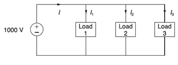
Figure 2.26 shows three loads connected in parallel across a
Load 1: Inductive load,
Load 2: Capacitive load,
Load 3: Resistive load,
(a) Determine the total kW, kvar, kva, and supply power factor.
(b) In order to improve the power factor to 0.8 lagging. a capacitor of negligible resistance is connected in parallel with the above loads. Find the kvar rating of that capacitor and the capacitance in
Comment on the magnitude of the supply current after adding the capacitor.

Trending nowThis is a popular solution!

Chapter 2 Solutions
MindTap Engineering, 1 term (6 months) Printed Access Card for Glover/Overbye/Sarma's Power System Analysis and Design, 6th


- In the system shown in Figure 1, the transformers are connected star-star with both star points grounded and the generators are connected in star with thier star points grounded. The system base is 15 MVA. The transformers all have reactances of 0.04 p.u. on this 15 MVA base. The reactances of all other elements are given in Table 1 (in 2) and the voltage levels are given in Table 2. p.u. G1 p.u. T1 jö Per-Unit Convert all values to p.u. on a 15 MVA base. Xa= p.u. Xc₂= XL = V BABE G1 2 X 9 T3 Figure 1: A section of the distribution system T1 L Table 1: Sequence reactances (2) 3 G1 L G2 0.3 0.59 0.01 4 L 9/10 10 Fault Voltage What is the voltage at bus 3 (in Volts) after the fault has occurred? Vp= V T2 5 T2 34 10/4 Table 2: Voltage bases (kV) G2 4 T3 10/9 | G2 Fault Current A three-phase fault with a fault reactance of 0.01 p.u. occurs at bus 3. Calculate the fault current flowing at the fault point in KA. Ip=-j KA Soarrow_forwardThe reactance of a generator is given as 0.1 pu based on the generator of 17 KV, 300 MVA. Determine the pu reactance on a base of 17 KV, 250 MVA. New pu reactance is.......arrow_forwardConsider the three single-phase two-winding transformers shown in Figure 3.37. The high-voltage windings are connected in Y. (a) For the low-voltage side, connect the windings in , place the polarity marks, and label the terminals a, b, and c in accordance with the American standard. (b) Relabel the terminals a, b, and c such that VAN is 90 out of phase with Va for positive sequence.arrow_forward
- A single-phase, 120V(rms),60Hz source supplies power to a series R-L circuit consisting of R=10 and L=40mH. (a) Determine the power factor of the circuit and state whether it is lagging or leading. (b) Determine the real and reactive power absorbed by the load. (c) Calculate the peak magnetic energy Wint stored in the inductor by using the expression Wint=L(Irms)2 and check whether the reactive power Q=Wint is satisfied. (Note: The instantaneous magnetic energy storage fluctuates between zero and the peak energy. This energy must be sent twice each cycle to the load from the source by means of reactive power flows.)arrow_forwardFor the single-phase circuit shown in Figure 2.22, I5 10/08A. (a) Compute the phasors I1, I2, and V. (b) Draw a phasor diagram showing I, I1 I2, and Varrow_forwarde = 0 Q1: What does happen if we change two currents? a. Q2: What does happen if we have a three-phase four poles machine? Q3: What does happen if we have a two-phase two poles machine? e = 0 Q4: What does happen if we apply a capacitance in phase b and then use same voltage for both phase. Dr. Ali Ki. pw --arrow_forward
- what are the advantages and Disadvantages Connecting transformers 3 Phase between (delta to Star)arrow_forwardNeed asap pls help. Solve for the voltages across and currents through each component. Show the complete solution and explain. The total power should be zero..arrow_forward(b) Differentiate between single phase and three phase alternating current (A.C) supply for the following aspects with adequate comparisons and sketches: (i) Generation of single phase and three phase e.m.f.s (ii) Sine waveforms(iii) Advantages or disadvantages of both phasesarrow_forward
- Two impedances consist of resistance of (15 ohms and series connectedinductance of 0.04 henry) and (resistance of 10 ohms, inductance of 0.1 henryand a capacitance of 100 microfarad, all in series) are connected in series andare connected to 230 volts, 50 – Hz AC source. Find: (a) current drawn, (b) voltageacross each impedance, (c) individual and total power factor. Draw the phasordiagram.arrow_forwardThe actual impedance of a load is 30 OHM. The per-unit impedance of the load is 0.5 pu when Base Voltage is 600 V and Base Power is O 6000 VA O 2000 VA O 4000 VA 8000 VAarrow_forwardAlternator A (100 kVA, 3-f, 240 V, 60 Hz, 1800 rpm) is operating in parallel with alternator B (125 kVA, 3-f, 240 V, 60 Hz, 1800 rpm). The load of alternator A is 70 kW at 85% pf leading and the load of alternator B is 85 kW at 75% pf leading. Determine the pf of load.arrow_forward
 Power System Analysis and Design (MindTap Course ...Electrical EngineeringISBN:9781305632134Author:J. Duncan Glover, Thomas Overbye, Mulukutla S. SarmaPublisher:Cengage Learning