
Concept explainers
Find three (or other number as assigned) of the following common devices. Sketch careful kinematic diagrams and find their total degrees of freedom.
- An automobile hood hinge
mechanism - An automobile hatchback lift mechanism
- An electric can opener
- A folding ironing board
- A folding card able
- A folding beach chair
- A baby swing
- A folding baby walker
- A fancy corkscrew as shown in Figure P2-9
- A windshield wiper mechanism
- A dump truck dump mechanism
- A trash truck dumpster mechanism
- A pickup truck tailgate mechanism
- An automobile jack
- A collapsible auto radio antenna
a.
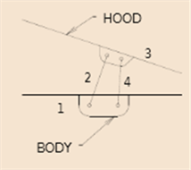
To find:Kinematic diagrams and total DOF in an automobile hood hinge mechanism.
Explanation of Solution
Given information:
The initial conditions that are given are that of an automobile hood hinge mechanism
Calculation:
Here KutzbatchEquation is used to compute mobility (DOF) of the shown system below. An automobile mechanism systemcondition is as shown.
b.
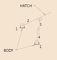
To find:Kinematic diagrams and total DOF inan automobile hatchback lift mechanism.
Explanation of Solution
Given information:
The initial conditions that are given are that of An automobile hatchback lift mechanism.
Calculation:
Here Kutzbatch Equation is used to compute mobility (DOF) the models below. Here mainly considering the given mechanism of an automobile hatchback lift mechanism which having the
c.
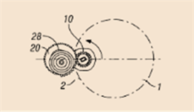
To find:Kinematic diagrams and total DOF in the electric can opener.
Explanation of Solution
Given information:
The initial conditions that are given are that of electric opener has 2 DOF.
Calculation:
Here Kutzbatch Equation is used to compute mobility (DOF) the given mechanismbelow. Here mainly considering the given mechanism of an electric opener has 2 DOF
d.
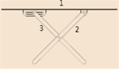
To find:Kinematic diagrams and total DOF in a folding ironing board.
Explanation of Solution
Given information:
The initial conditions that are given are that of a folding ironing board
Calculation:
Here Kutzbatch Equation is used to compute mobility (DOF) the given mechanism below.Here mainly considering the given mechanism A folding ironing board with One leg joins pivot joint on board and the other is slider joint.
e.
To find:Kinematic diagrams and total DOF in a folding card table.
Explanation of Solution
Given information:
The initial conditions that are given are that ofa folding card table.
Calculation:
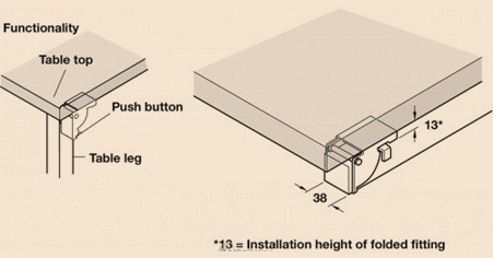
Here Kutzbatch Equation is used to compute mobility (DOF) the given mechanism below. A folding card table having 7 DOF for considering 1 for individual leg, 2 for x-ylocation and one for angular orientation.
f.
To find:Kinematic diagrams and total DOF in a folding beach chair.
Explanation of Solution
Given information:
The initial conditions that are given are that of a folding beach chair.
Calculation:
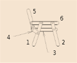
Here Kutzbatch Equation is used to compute mobility (DOF) the given mechanism below. A folding beach chair with ternary links having analysis below is Subtract 1 DOF forced stop.
g.
To find:Kinematic diagrams and total DOF in a baby swing.
Explanation of Solution
Given information:
The initial conditions that are given are that ofa baby swing.
Calculation:
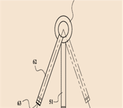
Here Kutzbatch Equation is used to compute mobility (DOF) the given mechanism below. A baby swing has 4 DOF,for swing 1 angular orientation w.r.t. frame, and 3 for location and orientation of the frame w.r.t. a 2-D frame.
h.
To find:Kinematic diagrams and total DOF in a folding baby walker.
Explanation of Solution
Given information:
The initial conditions that are given are that ofA folding baby walker
Calculation:
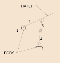
Here Kutzbatch Equation is used to compute mobility (DOF) the given mechanism below. A folding baby walker having 4 DOF with considering of 1 degree with unfolded, and 3 for the walkerlocation and orientation w.r.t.a 2-D frame.
i.
To find:Kinematic diagrams and total DOF in a fancy corkscrew.
Explanation of Solution
Given information:
The initial conditions that are given are that ofa fancy corkscrew.
Calculation:
Here Kutzbatch Equation is used to compute mobility (DOF) the given mechanism below. A fancy corkscrew having 2 DOF for screw rotated and arms rotate to translate w.r.t. screw.
j.
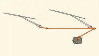
To find:Kinematic diagrams and total DOF in a windshield wiper mechanism.
Explanation of Solution
Given information:
The initial conditions that are given are that of A windshield wiper mechanism.
Calculation:
Here Kutzbatch Equation is used to compute mobility (DOF) the given mechanism below.A windshield wiper mechanism has 1 DOF with considering of the wiper blades position w.r.t. a single input.
k.
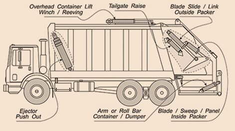
To find:Kinematic diagrams and total DOF in a dump truck mechanism.
Explanation of Solution
Given information:
The initial conditions that are given are that of. A dump-truck dump mechanism
Calculation:
Here Kutzbatch Equation is used to compute mobility (DOF) the given mechanism below.A dump-truck dump mechanism having 1 DOF for a angle of dump body for length of the hydraulic cylinder links w.r.t. the body truck.
l.
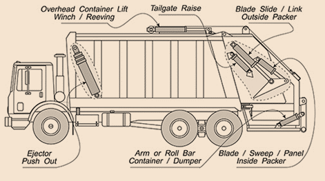
To find:Kinematic diagrams and total DOF in a trash truck mechanism.
Explanation of Solution
Given information:
The initial conditions that are given are that ofA trash truck dumpster mechanism
Calculation:
Here Kutzbatch Equation is used to compute mobility (DOF) the given mechanism below. A trash truck dumpster mechanism having 2 DOF for generally a rotation and a translation.
m.
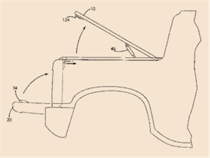
To find:Kinematic diagrams and to find their total DOF in a trash truck tailgate mechanism.
Explanation of Solution
Given information:
The initial conditions that are given are that ofa pickup tailgate mechanism.
Calculation:
Here Kutzbatch Equation is used to compute mobility (DOF) the given mechanism below. A pickup tailgate mechanism having a 1 DOF.
n.
To find:Kinematic diagrams and total DOF in an automobile jack.
Explanation of Solution
Given information:
The initial conditions that are given are that ofAn automobile jack mechanism.
Calculation:
Here Kutzbatch Equation is used to compute mobility (DOF) the given mechanism below. An automobile jack having 1 DOF for height jack and the other for the positionand orientation of the jack w.r.t. a 2-D frame.
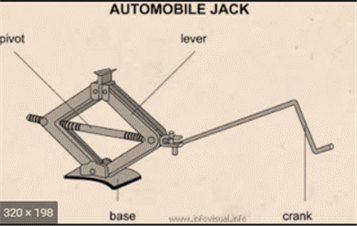
, total4 DOF
o.
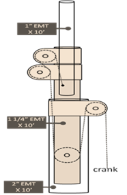
To find:Kinematic diagrams and total DOF in a collapsible auto radio antenna.
Explanation of Solution
Given information:
The initial conditions that are given are that ofa collapsible auto radio antenna mechanism.
Calculation:
Here Kutzbatch Equation is used to compute mobility (DOF) the given mechanism below. Amany DOF with considering section for a collapsible auto radio antenna, its less one.
Want to see more full solutions like this?
Chapter 2 Solutions
DESIGN OF MACHINERY
- The following shows the top view of the partially open doors on one side of an entertainment center cabinet. The wooden doors are hinged to each other and one door is hinged to the cabinet. There is also a ternary, metal link attached to the cabinet and door through pin joints. As spring- loaded piston-in-cylinder device attaches to the ternary link and the cabinet through pin joints. Draw a kinematic diagram of the door system and find the mobility of this mechanism. cylinder piston O cabinet link hinge door door hingearrow_forwardA series of three links is given with lengths of 2.4 ", 7.2" and 3.4 ", select the length of a fourth link, that when assembling the mechanism one of the links can be driven by a motor that rotates continuously. Mechanism is according to Grashoff, show all your operations to justify your resultsarrow_forwardFor the First name and Surame please use the N - Z option First name w(ab) and a(AB) are counter-clockwise Surname: r(AB) = 500mm and angle = 30 Degreesarrow_forward
- For the following figure, draw a kinematic diagram for each identifyingthe point of interest. From there, calculate the mobility of the device.arrow_forwardi need the final answer quickk plsarrow_forward4. Four identical SRS arms are grasping a common object as shown below. Spherical Joint Revolute Joint Find the number of degrees of freedom of this system while the grippers hold the object rigidly (no relative motion between the object and the last links of the SRS arms). Your answer should be an integer. Enter answer here 5. Referring back to Question 4, suppose there are now a total of n such arms grasping the object. What is the number of degrees of freedom of this system? Your answer should be a mathematical expression including n. Examples of mathematical expressions including n are 4 n-7 or n/3.arrow_forward
- The length of the links are known for the mechanism shown in Figure. The angle of driver link 1 with the horizontal is ϕ= ϕ1 and the angular speed of driver link 1 is n = n1. The input data for ten cases are given in the table in Figure. Determine:a) the number of DOF of the mechanism.b) the positions of joints B, C, D, and E for a complete rotation of driver link 1,ϕ=[330°].c) the linear velocities of joints B, C, D, E and the angular velocities of links 2,3, and 4 for a complete rotation of driver link 1, ϕ=[ 330°].d) the linear accelerations of joints B, C, D, E, and the angular accelerations of links 2,3, and 4 for a complete rotation of driver link 1, ϕ=[ 330°].arrow_forwardneed help getting the correct answe pleasearrow_forwardPlease help me with this Kinematics problem. This is for kinematics & dynamics of machines. Thank you.arrow_forward
- MANUFACTURING COMPONENT DESIGarrow_forwardB3. SOLVE STEP BY STEP IN DIGITAL FORMAT A set of sprockets is constructed, as shown in Figure 1, so that the second and third rotate on a common axis. When the first rotates, it drives the second and this in turn drives the third. Let and be the numbers of revolutions per minute of the first, second, and third axes. dy du dy dy dtu Find www.du' dx' and, and verify that dr du Figure 1 |1cm axis 1 |- 4cm -| axis 2 axis 1: y rev per minute axis 2: u rev per minute axis 3: x rev per minute |1e| |- 3cm-|| axis 3arrow_forwardHand written plz asap... I'll give you multiple upvote hand written plz... Plz solve it within 1 hour plzzz fast...arrow_forward
 Elements Of ElectromagneticsMechanical EngineeringISBN:9780190698614Author:Sadiku, Matthew N. O.Publisher:Oxford University Press
 Mechanics of Materials (10th Edition)Mechanical EngineeringISBN:9780134319650Author:Russell C. HibbelerPublisher:PEARSON
 Thermodynamics: An Engineering ApproachMechanical EngineeringISBN:9781259822674Author:Yunus A. Cengel Dr., Michael A. BolesPublisher:McGraw-Hill Education
 Control Systems EngineeringMechanical EngineeringISBN:9781118170519Author:Norman S. NisePublisher:WILEY
 Mechanics of Materials (MindTap Course List)Mechanical EngineeringISBN:9781337093347Author:Barry J. Goodno, James M. GerePublisher:Cengage Learning
 Engineering Mechanics: StaticsMechanical EngineeringISBN:9781118807330Author:James L. Meriam, L. G. Kraige, J. N. BoltonPublisher:WILEY


