Elements Of Electromagnetics
7th Edition
ISBN: 9780190698614
Author: Sadiku, Matthew N. O.
Publisher: Oxford University Press
expand_more
expand_more
format_list_bulleted
Question
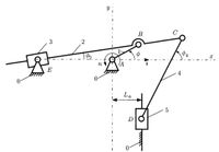
The length of the links are known for the
driver link 1 with the horizontal is ϕ= ϕ1 and the angular speed of driver link 1 is n =
n1. The input data for ten cases are given in the table in Figure. Determine:
a) the number of DOF of the mechanism.
b) the positions of joints B, C, D, and E for a complete rotation of driver link 1,
ϕ=[330°].
c) the linear velocities of joints B, C, D, E
and the angular velocities of links 2,3,
and 4 for a complete rotation of driver
link 1, ϕ=[ 330°].
d) the linear accelerations of joints B, C, D,
E, and the angular accelerations of links
2,3, and 4 for a complete rotation of
driver link 1, ϕ=[ 330°].

Expert Solution
This question has been solved!
Explore an expertly crafted, step-by-step solution for a thorough understanding of key concepts.
Step by stepSolved in 3 steps with 1 images

Knowledge Booster
Learn more about
Need a deep-dive on the concept behind this application? Look no further. Learn more about this topic, mechanical-engineering and related others by exploring similar questions and additional content below.Similar questions
- A general pinjointed fourbar linkage is shown in the figure below. It has the followings: The link lengths are L1 = 8.50 in., L2 = 3.00 in., L3 = 5.00 in. and L4 = 4.50 in. The values of θ1 = 0, θ2 = 60°, and θ4 = 119°. The angular velocity of link2 ω2 = 10 rad/s CCW. The angular velocities of link 3 ω3 and and link 4 ω4 are: Select one: a. ω3 = 5.29 rad/s CW, ω4 = 4.80 rad/s CCW b. ω3 = 5.29rad/s CW, ω4 = 6.14 rad/s CW c. ω3 = 3.94 rad/s CCW, ω4 = 4.8 rad/s CCW d. ω3 = 3.94 rad/s CCW, ω4 = 6.14 rad/s CCWarrow_forwardPlease dont provide this handwritten solution...arrow_forwardAnalytically determine the linear displacement of the piston in the compressor linkage shown in the figure as the 45 mm. crank is rotated from its current position 90 degree clockwise.arrow_forward
- Please solve 509 and 510, thanks!arrow_forwardPls urgenttarrow_forwardIn the mechanism shown in figure. The angular velocity of link 2 is 100 rad/sec. CCW. Use loop closure and time derivative method for this analysis. Solve for w3 at instant when 02 = 90°. Use matrix formulation to solve the equations. Also solve for the velocity of point D at the instant 0₂ = 90°. B A 3 AB = 1.75 in AC = 2.5 in BD = 5 inarrow_forward
- The following shows the top view of the partially open doors on one side of an entertainment center cabinet. The wooden doors are hinged to each other and one door is hinged to the cabinet. There is also a ternary, metal link attached to the cabinet and door through pin joints. As spring- loaded piston-in-cylinder device attaches to the ternary link and the cabinet through pin joints. Draw a kinematic diagram of the door system and find the mobility of this mechanism. cylinder piston O cabinet link hinge door door hingearrow_forwardI need her solving with conting on the graph Link and j1 and j2 pls quickkarrow_forwardA 20-in diameter rotates at 200 RPM and a 40-in diameter pulley are used with an open belt to connect two shafts 6 ft. apart. Determine the length (inches) and speed of the belt (FPM). PLLEASE PROVIDE ILLUSTRATIONarrow_forward
- Pls i need her solve quickkk plssarrow_forwardEvaluate the 3-DOF wrist as shown in Figure 2, use the conventional method to determine 1. Linear velocity and 2. Angular velocity NOTE: for JOINT 3 ( 03 ) only Connected to robot arm Pitch Roll Yaw Figure 2: Wrist assembly The known position and orientation of the end of the arm point is. C, C2 [-C,S2C3 + S¼S3 -S;S2C3 – C1S3 C2C3 C¡S2S3 + S1C3 S4S2S3 + C,C3 -C2S3 01 S,C2 S2 1 °T3=°T¡'T2²T3arrow_forward1. Figure 4.11 shows a kinematic diagram of a mechanism that is driven by moving link Graphically reposition the links of the mechanism as link 2 is displaced 30° counterclockwise. Determine the resulting angular displacement of link 4 and the linear displacement of point. B 3″ AD 4.9" 90° 0 5.3" 3.3" 10.1" D 3.2"arrow_forward
arrow_back_ios
SEE MORE QUESTIONS
arrow_forward_ios
Recommended textbooks for you
 Elements Of ElectromagneticsMechanical EngineeringISBN:9780190698614Author:Sadiku, Matthew N. O.Publisher:Oxford University Press
 Mechanics of Materials (10th Edition)Mechanical EngineeringISBN:9780134319650Author:Russell C. HibbelerPublisher:PEARSON
 Thermodynamics: An Engineering ApproachMechanical EngineeringISBN:9781259822674Author:Yunus A. Cengel Dr., Michael A. BolesPublisher:McGraw-Hill Education
 Control Systems EngineeringMechanical EngineeringISBN:9781118170519Author:Norman S. NisePublisher:WILEY
 Mechanics of Materials (MindTap Course List)Mechanical EngineeringISBN:9781337093347Author:Barry J. Goodno, James M. GerePublisher:Cengage Learning
 Engineering Mechanics: StaticsMechanical EngineeringISBN:9781118807330Author:James L. Meriam, L. G. Kraige, J. N. BoltonPublisher:WILEY

Elements Of Electromagnetics
Mechanical Engineering
ISBN:9780190698614
Author:Sadiku, Matthew N. O.
Publisher:Oxford University Press

Mechanics of Materials (10th Edition)
Mechanical Engineering
ISBN:9780134319650
Author:Russell C. Hibbeler
Publisher:PEARSON

Thermodynamics: An Engineering Approach
Mechanical Engineering
ISBN:9781259822674
Author:Yunus A. Cengel Dr., Michael A. Boles
Publisher:McGraw-Hill Education

Control Systems Engineering
Mechanical Engineering
ISBN:9781118170519
Author:Norman S. Nise
Publisher:WILEY

Mechanics of Materials (MindTap Course List)
Mechanical Engineering
ISBN:9781337093347
Author:Barry J. Goodno, James M. Gere
Publisher:Cengage Learning

Engineering Mechanics: Statics
Mechanical Engineering
ISBN:9781118807330
Author:James L. Meriam, L. G. Kraige, J. N. Bolton
Publisher:WILEY