Concept explainers
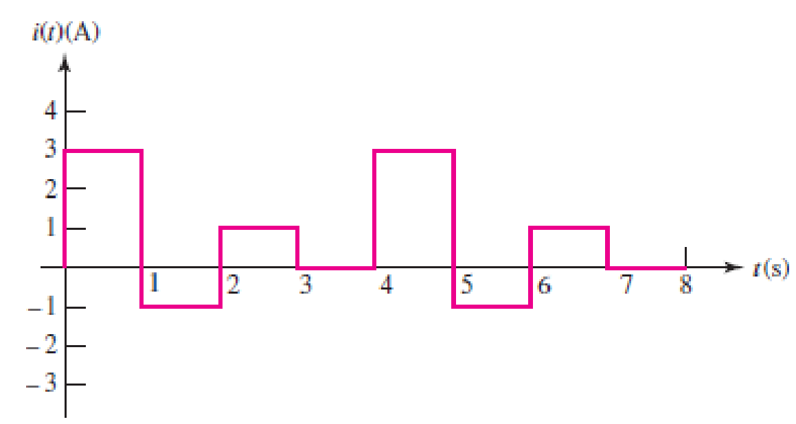
The current waveform depicted in Fig. 2.29 is characterized by a period of 4 s. (a) What is the average value of the current over a single period? (b) Compute the average current over the interval 1 < t < 3 s. (c) If q(0) = 1C, sketch q(t), 0 < t < 4 s.

FIGURE 2.29 An example of a time-varying current.
(a)
Find the average value of the given current waveform in Figure 2.29 over the period of 4 s.
Answer to Problem 21E
The average value of the given current waveform over the period of 4 s is
Explanation of Solution
Given data:
Refer to Figure 2.29 in textbook for the time-varying current with the period of 4 s.
Formula used:
Write the formula to find the average value of a function of current over a period as,
Here,
T is the time period.
Calculation:
From the given current waveform in Figure 2.29, the function of current
For the period of
For the period of
For the period of
For the period of
Therefore, the final function of current
The average value of current
Reduce the equation as follows.
Conclusion:
Thus, the average value of the given current waveform over the period of 4 s is
(b)
Find the average current of the waveform over the period of
Answer to Problem 21E
The average current of the waveform over the period of
Explanation of Solution
Given data:
Refer to part (a).
Formula used:
Write the formula to find the average value of a function of current over a period of
Here,
Calculation:
Write the function of current
Now, the average current of
Conclusion:
Thus, the average current of the waveform over the period of
(c)
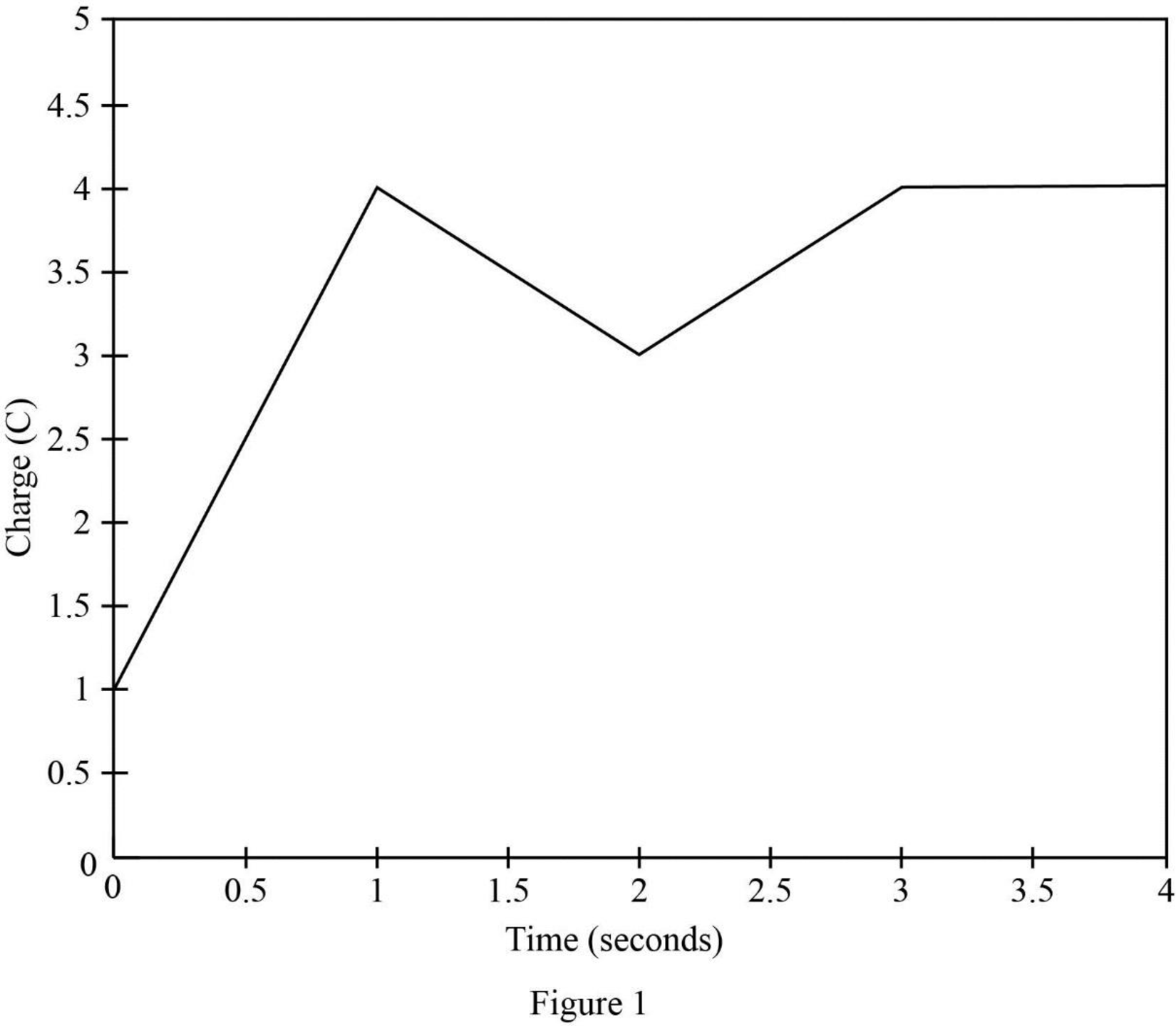
Sketch the waveform for the charge
Explanation of Solution
Given data:
Refer to part (a).
The initial charge
Formula used:
Write the expression for the relation between charge
Integrate the above equation on both sides.
Calculation:
Using the function of
For
Substitute 3 A for
Substitute 1 C for
Substitute 1 for
For
For the period of
Substitute –1 A for
Substitute 4 C for
Substitute 2 for
For
For the period of
Substitute 1 A for
Substitute 3 C for
Substitute 3 for
For
For the period of
Substitute 0 A for
Substitute 4 C for
Therefore, the charge
Table 1 shows for
Table 1
| t in seconds | |
| 0 | 1 |
| 1 | 4 |
| 2 | 2 |
| 3 | 4 |
| 4 | 4 |
Figure 1 shows the charge (C) vs time (s) waveform.

Conclusion:
Thus, the waveform for the charge
Want to see more full solutions like this?
Chapter 2 Solutions
Loose Leaf for Engineering Circuit Analysis Format: Loose-leaf
- Please solve in detailarrow_forward6.7 The transmitting aerial shown in Fig. Q.3 is supplied with current at 80 A peak and at frequency 666.66 kHz. Calculate (a) the effective height of the aerial, and (b) the electric field strength produced at ground level 40 km away. 60 m Fig. Q.3 Input 48 m Eartharrow_forwardox SIM 12.11 Consider the class B output stage, using MOSFETs, shown in Fig. P12.11. Let the devices have |V|= 0.5 V and μC WIL = 2 mA/V². With a 10-kHz sine-wave input of 5-V peak and a high value of load resistance, what peak output would you expect? What fraction of the sine-wave period does the crossover interval represent? For what value of load resistor is the peak output voltage reduced to half the input? Figure P12.11 +5 V Q1 Q2 -5Varrow_forward
- 4 H ་་་་་་་ 四一周 A H₂ Find out put c I writ R as a function G, H, Harrow_forward4 H A H₂ 四一周 Find out put c I writ R as a function G, H, Harrow_forward8. (a) In a Round-Robin tournament, the Tigers beat the Blue Jays, the Tigers beat the Cardinals, the Tigers beat the Orioles, the Blue Jays beat the Cardinals, the Blue Jays beat the Orioles and the Cardinals beat the Orioles. Model this outcome with a directed graph. https://www.akubihar.com (b) (c) ✓ - Let G = (V, E) be a simple graph. Let R be the relation on V consisting of pairs of vertices (u, v) such that there is a path from u to vor such that u= v. Show that R is an equivalence relation. 3 3 Determine whether the following given pair of directed graphs, shown in Fig. 1 and Fig. 2, are isomorphic or not. Exhibit an isomorphism or provide a rigorous argument that none exists. 4+4=8 Աշ աշ ИНИЯ Fig. 1 Fig. 2 Querarrow_forward
- EXAMPLE 4.5 Objective: Determine ID, circuit. V SG' SD Vs and the small - signal voltage gain of a PMOS transistor Consider the circuit shown in Figure 4.20(a). The transistor parameters are A K = 0.80m- V Р _2’TP = 0.5V, and λ = 0 Varrow_forwardNeed a solution and don't use chatgptarrow_forwardNeed a solarrow_forward
- Do not use chaarrow_forwardIn the following table, the value of 40 resistors are recorded in ohms. (a) Construct the frequency distribution table using number of class=5. (b) Plot the histogram of frequency table. 45 50 61 32 25 50 64 28 40 40 46 47 48 35 58 35 54 38 68 76 19 63 26 65 54 42 68 47 53 36 73 44 49 35 38 42 56 44 45 57arrow_forwardcircuit source transformation step by step v0 findarrow_forward
 Introductory Circuit Analysis (13th Edition)Electrical EngineeringISBN:9780133923605Author:Robert L. BoylestadPublisher:PEARSON
 Delmar's Standard Textbook Of ElectricityElectrical EngineeringISBN:9781337900348Author:Stephen L. HermanPublisher:Cengage Learning
 Programmable Logic ControllersElectrical EngineeringISBN:9780073373843Author:Frank D. PetruzellaPublisher:McGraw-Hill Education
 Fundamentals of Electric CircuitsElectrical EngineeringISBN:9780078028229Author:Charles K Alexander, Matthew SadikuPublisher:McGraw-Hill Education
 Electric Circuits. (11th Edition)Electrical EngineeringISBN:9780134746968Author:James W. Nilsson, Susan RiedelPublisher:PEARSON
 Engineering ElectromagneticsElectrical EngineeringISBN:9780078028151Author:Hayt, William H. (william Hart), Jr, BUCK, John A.Publisher:Mcgraw-hill Education,


