
Physics: Principles with Applications
7th Edition
ISBN: 9780321625922
Author: Douglas C. Giancoli
Publisher: Addison-Wesley
expand_more
expand_more
format_list_bulleted
Videos
Textbook Question
Chapter 19, Problem 26P
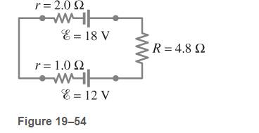
Determine the terminal voltage of each battery in Fig. 19-54.
Expert Solution & Answer
Want to see the full answer?
Check out a sample textbook solution
Students have asked these similar questions
A flashlight bulb rated at 2.0 W and 3.0 V is operated by
a 9.0-V battery. To light the bulb at its
rated voltage and power, a resistor R is
connected in series as shown
in Fig. 19–85. What value
should the resistor have?
R
FIGURE 19-85
Problem 87.
9.0 V
A 12.0-V battery, two resistors, and two capacitors are
connected as shown in Fig. 19–87. After the circuit has
been connected for a long time, what is the charge on each
сараcitor?
1.3 k2
12.0 V=
12 μF
- 48 μF
3.3 k2
FIGURE 19-87 Problem 89.
For the circuit shown in Fig. 19–80, determine (a) the
current through the 16-V battery and (b) the potential
difference between
13 k2 b
10 k2
a
points a and b,
Va - Vp.
16 V=
- 21 V
FIGURE 19-80
Problem 82.
12 V
ww
18 k2
12 k2
Chapter 19 Solutions
Physics: Principles with Applications
Ch. 19 - Prob. 1OQCh. 19 - Prob. 1QCh. 19 - Prob. 2QCh. 19 - Prob. 3QCh. 19 - Prob. 4QCh. 19 - Prob. 5QCh. 19 - Prob. 6QCh. 19 - Prob. 7QCh. 19 - Prob. 8QCh. 19 - Prob. 9Q
Ch. 19 - Prob. 10QCh. 19 - Prob. 11QCh. 19 - Prob. 12QCh. 19 - Prob. 13QCh. 19 - Prob. 14QCh. 19 - Prob. 15QCh. 19 - Given the circuit shown in Fig. 19-38, use the...Ch. 19 - Prob. 17QCh. 19 - Prob. 18QCh. 19 - 19. What is the main difference between an analog...Ch. 19 - What would happen if you mistakenly used an...Ch. 19 - Prob. 21QCh. 19 - Prob. 22QCh. 19 - Prob. 23QCh. 19 - Prob. 1MCQCh. 19 - Prob. 2MCQCh. 19 - Prob. 3MCQCh. 19 - Prob. 4MCQCh. 19 - Prob. 5MCQCh. 19 - Prob. 6MCQCh. 19 - Prob. 7MCQCh. 19 - Prob. 8MCQCh. 19 - Prob. 9MCQCh. 19 - Prob. 10MCQCh. 19 - Prob. 11MCQCh. 19 - Prob. 12MCQCh. 19 - Prob. 13MCQCh. 19 - Prob. 14MCQCh. 19 - Prob. 15MCQCh. 19 - Calculate the terminal voltage for a battery with...Ch. 19 - Prob. 2PCh. 19 - What is the internal resistance of a 12.0-V car...Ch. 19 - A 650-O and an 1800-O resistor are connected in...Ch. 19 - Prob. 5PCh. 19 - Suppose that you have a 580-O, a 790-O, and a...Ch. 19 - Prob. 7PCh. 19 - Prob. 8PCh. 19 - Prob. 9PCh. 19 - Prob. 10PCh. 19 - Prob. 11PCh. 19 - Eight identical bulbs are connected in series...Ch. 19 - Prob. 13PCh. 19 - Prob. 14PCh. 19 - Prob. 15PCh. 19 - Determine (a) the equivalent resistance of the...Ch. 19 - Prob. 17PCh. 19 - (a) Determine the equivalent resistance of the...Ch. 19 - What is the net resistance of the circuit...Ch. 19 - Prob. 20PCh. 19 - Prob. 21PCh. 19 - Prob. 22PCh. 19 - Prob. 23PCh. 19 - Consider the network of resistors shown in Fig....Ch. 19 - Calculate the current in the circuit of Fig....Ch. 19 - Determine the terminal voltage of each battery in...Ch. 19 - For the circuit shown in Fig.19-55, find the...Ch. 19 - Determine the magnitudes and directions of the...Ch. 19 - (a) What is the potential difference between...Ch. 19 - Prob. 30PCh. 19 - 31. (II) Determine the magnitudes V1= 9.0 V R1, =...Ch. 19 - Prob. 32PCh. 19 - Prob. 33PCh. 19 - (a) Determine the currents l1,l2 and l3 in Fig....Ch. 19 - Prob. 35PCh. 19 - Prob. 36PCh. 19 - Prob. 37PCh. 19 - Prob. 38PCh. 19 - A 3.00-F and a 4.00-F capacitor are connected in...Ch. 19 - If 21.0 V is applied across the whole network of...Ch. 19 - The capacitance of a portion of a circuit is to be...Ch. 19 - An electric circuit was accidentally constructed...Ch. 19 - Consider three capacitors, of capacitance 3200...Ch. 19 - Determine the equivalent capacitance between...Ch. 19 - What is the ration of the voltage V1 across...Ch. 19 - A 0.50-F and a 1.4-F capacitor are connected in...Ch. 19 - A circuit contains a single 250-pF capacitor...Ch. 19 - Prob. 48PCh. 19 - Prob. 49PCh. 19 - Given three capacitors. C1= 2.0$ mUF, C2= 1.5 F,...Ch. 19 - Prob. 51PCh. 19 - Prob. 52PCh. 19 - Prob. 53PCh. 19 - In Fig. 19-69 (same as Fig. 19-20a ), the total...Ch. 19 - Prob. 55PCh. 19 - Prob. 56PCh. 19 - Prob. 57PCh. 19 - Two resistors and two uncharged capacitors are...Ch. 19 - Prob. 59PCh. 19 - Prob. 60PCh. 19 - Prob. 61PCh. 19 - A galvanometer has an internal resistance of 32 ...Ch. 19 - Prob. 63PCh. 19 - Prob. 64PCh. 19 - Prob. 65PCh. 19 - Prob. 66PCh. 19 - Prob. 67GPCh. 19 - Prob. 68GPCh. 19 - Prob. 69GPCh. 19 - Prob. 70GPCh. 19 - A heart pacemaker is designed to operate at 72...Ch. 19 - Prob. 72GPCh. 19 - Prob. 73GPCh. 19 - Prob. 74GPCh. 19 - Prob. 75GPCh. 19 - Prob. 76GPCh. 19 - Prob. 77GPCh. 19 - Prob. 78GPCh. 19 - Prob. 79GPCh. 19 - Prob. 80GPCh. 19 - Prob. 81GPCh. 19 - Prob. 82GPCh. 19 - Prob. 83GPCh. 19 - (a) What is the equivlaent resistance of the...Ch. 19 - Prob. 85GPCh. 19 - Prob. 86GPCh. 19 - Prob. 87GPCh. 19 - In Fig. 19-86, let V= 10.0 V and C1=C2=C3=25.4 F....Ch. 19 - 89. A 12.0-V battery, two resistors, and two...Ch. 19 - Prob. 90GPCh. 19 - Prob. 91GPCh. 19 - Prob. 92GPCh. 19 - Prob. 93GPCh. 19 - Prob. 94GPCh. 19 - The variable capacitance of an old radio tuner...Ch. 19 - Prob. 96GPCh. 19 - Prob. 97GP
Knowledge Booster


Learn more about
Need a deep-dive on the concept behind this application? Look no further. Learn more about this topic, physics and related others by exploring similar questions and additional content below.Similar questions
- - (III) (a) A network of five equal resistors R is connected to a battery & as shown in Fig. 19–60. Determine the current I that flows out of the R battery. (b) Use the value determined for I to find the wwww W R ww single resistor Req that is equivalent R R to the five-resistor R network. FIGURE 19-60 Problem 33.arrow_forward-37 In Fig. 27-48, the resistances are R, = 2.00 N, R, = 5.00 N, and the battery is ideal. What value of R3 Ra R3 maximizes the dissipation rate in resistance 3? wwarrow_forward(III) (a) Determine the currents I, 1,, and Iz in Fig. 19–61. Assume the internal resistance of each battery is r = 1.0 N. (b) What is the terminal voltage of the 6.0-V battery? 12.0 V 22 Ω 12 2 28 Ω |12.0 V 11Ω 16 2 FIGURE 19–61 Problems 34 and 35. 6.0 V I3 wwarrow_forward
- (II) What is the net resistance of the circuit connected to the battery in Fig. 19–50? R R C ww B ww R V R FIGURE 19-50 R A Problems 19 and 20. wwarrow_forwardRefer to the portion of a circuit given in Fig. 18-16. What is the potential difference? V_A - V_B If I = 5.0arrow_forward(II) For the circuit shown in Fig. 19–55, find the potential difference between points a and b. Each resistor has R R = 160 N and each bat- tery is 1.5 V. a 1.5 V• R: R R 1.5 V FIGURE 19-55 Problem 27. barrow_forward
- Calculate the magnitude and direction of the durrents in each resistor of fig. 19-58. There are two solutions to this problem given on the website. However, both are leaveing out steps.arrow_forward(III) When the resistor R in Fig. 19-73 is 35 N, the high- resistance voltmeter reads 9.7 V. When R is replaced by a 14.0-N resistor, the voltmeter reading drops to 8.1 V. What are the emf and V internal resistance of the battery? ww R FIGURE 19–73 Problem 66.arrow_forward(a) In Fig. 25-19a, are capacitors 1 and 3 in series? (b) In the same (a) (b) (c) (d) HHarrow_forward
- (I) Calculate the current in the circuit of Fig. 19–53, and show that the sum of all the r= 2.0 2 voltage changes around the circuit is zero. 9.0 V 9.5 Q FIGURE 19–53 Problem 25. 14.0 2arrow_forwardTe-Learning Portal Courses - Reports e-Services ▼ Academic Departments - ETC - CIMS Salim During an experiment to verify Ohm's law, the voltage supplied and the current through a circuit are measured. [Voltage is measured in Volt (V) and current in Ampere (A)]. ww R on Battery The measured value of the current is I = 3.1 ± 0.2 A and that of the voltage is V = 14 0.5 V. The resistance of the circuit (in N) can be calculated using the formula, R = V/I, Calculate the, a) Resistance (in 2) = b) Fractional uncertainty in the resistance = c) Absolute uncertainty (in 2) in the resistance=arrow_forwardA three-way lightbulb can produce 50 W, 100 W, or 150 W, at 120 V. Such a bulb contains two filaments that can be connected to the 120 V individually or in parallel (Fig. 19–74). (a) Describe how the connections to the two filaments are made to give each of the three wattages. (b) What must be the resistance of each filament? FIGURE 19–74 Problem 68.arrow_forward
arrow_back_ios
SEE MORE QUESTIONS
arrow_forward_ios
Recommended textbooks for you

How To Solve Any Resistors In Series and Parallel Combination Circuit Problems in Physics; Author: The Organic Chemistry Tutor;https://www.youtube.com/watch?v=eFlJy0cPbsY;License: Standard YouTube License, CC-BY