
Physics: Principles with Applications
7th Edition
ISBN: 9780321625922
Author: Douglas C. Giancoli
Publisher: Addison-Wesley
expand_more
expand_more
format_list_bulleted
Videos
Textbook Question
Chapter 19, Problem 25P
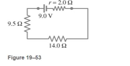
Calculate the current in the circuit of Fig. 19-53,  and show that the sum of all the voltage changes around the circuit is zero.
Expert Solution & Answer
Want to see the full answer?
Check out a sample textbook solution
Students have asked these similar questions
A flashlight bulb rated at 2.0 W and 3.0 V is operated by
a 9.0-V battery. To light the bulb at its
rated voltage and power, a resistor R is
connected in series as shown
in Fig. 19–85. What value
should the resistor have?
R
FIGURE 19-85
Problem 87.
9.0 V
(III) When the resistor R in Fig. 19-73 is 35 N, the high-
resistance voltmeter reads 9.7 V. When R is replaced by a
14.0-N resistor, the voltmeter
reading drops to 8.1 V.
What are the emf and
V
internal resistance of
the battery?
ww
R
FIGURE 19–73
Problem 66.
Calculate the magnitude and direction of the durrents in each resistor of fig. 19-58.
There are two solutions to this problem given on the website. However, both are leaveing out steps.
Chapter 19 Solutions
Physics: Principles with Applications
Ch. 19 - Prob. 1OQCh. 19 - Prob. 1QCh. 19 - Prob. 2QCh. 19 - Prob. 3QCh. 19 - Prob. 4QCh. 19 - Prob. 5QCh. 19 - Prob. 6QCh. 19 - Prob. 7QCh. 19 - Prob. 8QCh. 19 - Prob. 9Q
Ch. 19 - Prob. 10QCh. 19 - Prob. 11QCh. 19 - Prob. 12QCh. 19 - Prob. 13QCh. 19 - Prob. 14QCh. 19 - Prob. 15QCh. 19 - Given the circuit shown in Fig. 19-38, use the...Ch. 19 - Prob. 17QCh. 19 - Prob. 18QCh. 19 - 19. What is the main difference between an analog...Ch. 19 - What would happen if you mistakenly used an...Ch. 19 - Prob. 21QCh. 19 - Prob. 22QCh. 19 - Prob. 23QCh. 19 - Prob. 1MCQCh. 19 - Prob. 2MCQCh. 19 - Prob. 3MCQCh. 19 - Prob. 4MCQCh. 19 - Prob. 5MCQCh. 19 - Prob. 6MCQCh. 19 - Prob. 7MCQCh. 19 - Prob. 8MCQCh. 19 - Prob. 9MCQCh. 19 - Prob. 10MCQCh. 19 - Prob. 11MCQCh. 19 - Prob. 12MCQCh. 19 - Prob. 13MCQCh. 19 - Prob. 14MCQCh. 19 - Prob. 15MCQCh. 19 - Calculate the terminal voltage for a battery with...Ch. 19 - Prob. 2PCh. 19 - What is the internal resistance of a 12.0-V car...Ch. 19 - A 650-O and an 1800-O resistor are connected in...Ch. 19 - Prob. 5PCh. 19 - Suppose that you have a 580-O, a 790-O, and a...Ch. 19 - Prob. 7PCh. 19 - Prob. 8PCh. 19 - Prob. 9PCh. 19 - Prob. 10PCh. 19 - Prob. 11PCh. 19 - Eight identical bulbs are connected in series...Ch. 19 - Prob. 13PCh. 19 - Prob. 14PCh. 19 - Prob. 15PCh. 19 - Determine (a) the equivalent resistance of the...Ch. 19 - Prob. 17PCh. 19 - (a) Determine the equivalent resistance of the...Ch. 19 - What is the net resistance of the circuit...Ch. 19 - Prob. 20PCh. 19 - Prob. 21PCh. 19 - Prob. 22PCh. 19 - Prob. 23PCh. 19 - Consider the network of resistors shown in Fig....Ch. 19 - Calculate the current in the circuit of Fig....Ch. 19 - Determine the terminal voltage of each battery in...Ch. 19 - For the circuit shown in Fig.19-55, find the...Ch. 19 - Determine the magnitudes and directions of the...Ch. 19 - (a) What is the potential difference between...Ch. 19 - Prob. 30PCh. 19 - 31. (II) Determine the magnitudes V1= 9.0 V R1, =...Ch. 19 - Prob. 32PCh. 19 - Prob. 33PCh. 19 - (a) Determine the currents l1,l2 and l3 in Fig....Ch. 19 - Prob. 35PCh. 19 - Prob. 36PCh. 19 - Prob. 37PCh. 19 - Prob. 38PCh. 19 - A 3.00-F and a 4.00-F capacitor are connected in...Ch. 19 - If 21.0 V is applied across the whole network of...Ch. 19 - The capacitance of a portion of a circuit is to be...Ch. 19 - An electric circuit was accidentally constructed...Ch. 19 - Consider three capacitors, of capacitance 3200...Ch. 19 - Determine the equivalent capacitance between...Ch. 19 - What is the ration of the voltage V1 across...Ch. 19 - A 0.50-F and a 1.4-F capacitor are connected in...Ch. 19 - A circuit contains a single 250-pF capacitor...Ch. 19 - Prob. 48PCh. 19 - Prob. 49PCh. 19 - Given three capacitors. C1= 2.0$ mUF, C2= 1.5 F,...Ch. 19 - Prob. 51PCh. 19 - Prob. 52PCh. 19 - Prob. 53PCh. 19 - In Fig. 19-69 (same as Fig. 19-20a ), the total...Ch. 19 - Prob. 55PCh. 19 - Prob. 56PCh. 19 - Prob. 57PCh. 19 - Two resistors and two uncharged capacitors are...Ch. 19 - Prob. 59PCh. 19 - Prob. 60PCh. 19 - Prob. 61PCh. 19 - A galvanometer has an internal resistance of 32 ...Ch. 19 - Prob. 63PCh. 19 - Prob. 64PCh. 19 - Prob. 65PCh. 19 - Prob. 66PCh. 19 - Prob. 67GPCh. 19 - Prob. 68GPCh. 19 - Prob. 69GPCh. 19 - Prob. 70GPCh. 19 - A heart pacemaker is designed to operate at 72...Ch. 19 - Prob. 72GPCh. 19 - Prob. 73GPCh. 19 - Prob. 74GPCh. 19 - Prob. 75GPCh. 19 - Prob. 76GPCh. 19 - Prob. 77GPCh. 19 - Prob. 78GPCh. 19 - Prob. 79GPCh. 19 - Prob. 80GPCh. 19 - Prob. 81GPCh. 19 - Prob. 82GPCh. 19 - Prob. 83GPCh. 19 - (a) What is the equivlaent resistance of the...Ch. 19 - Prob. 85GPCh. 19 - Prob. 86GPCh. 19 - Prob. 87GPCh. 19 - In Fig. 19-86, let V= 10.0 V and C1=C2=C3=25.4 F....Ch. 19 - 89. A 12.0-V battery, two resistors, and two...Ch. 19 - Prob. 90GPCh. 19 - Prob. 91GPCh. 19 - Prob. 92GPCh. 19 - Prob. 93GPCh. 19 - Prob. 94GPCh. 19 - The variable capacitance of an old radio tuner...Ch. 19 - Prob. 96GPCh. 19 - Prob. 97GP
Knowledge Booster


Learn more about
Need a deep-dive on the concept behind this application? Look no further. Learn more about this topic, physics and related others by exploring similar questions and additional content below.Similar questions
- (I) Calculate the current in the circuit of Fig. 19–53, and show that the sum of all the r= 2.0 2 voltage changes around the circuit is zero. 9.0 V 9.5 Q FIGURE 19–53 Problem 25. 14.0 2arrow_forward(II) For the circuit shown in Fig. 19–55, find the potential difference between points a and b. Each resistor has R R = 160 N and each bat- tery is 1.5 V. a 1.5 V• R: R R 1.5 V FIGURE 19-55 Problem 27. barrow_forwardDesign a circuit in which two different switches of the type shown in Fig. 19–39 can be used to operate the same lightbulb from opposite sides of a Wire Wire room. FIGURE 19-39 Wire Question 17.arrow_forward
- For the circuit shown in Fig. 19–80, determine (a) the current through the 16-V battery and (b) the potential difference between 13 k2 b 10 k2 a points a and b, Va - Vp. 16 V= - 21 V FIGURE 19-80 Problem 82. 12 V ww 18 k2 12 k2arrow_forwardRefer to the portion of a circuit given in Fig. 18-16. What is the potential difference? V_A - V_B If I = 5.0arrow_forwardGiven the circuit shown in Fig. 19–38, use the words "increases," "decreases," or "stays the same" to complete the following statements: (a) If R, increases, the potential difference between A and - Assume no resistance in O and E. (b) If R, increases, the potential difference between A and Assume O and E have resistance. E E (c) If R, increases, the voltage drop across R4 (d) If R2 decreases, the current through R1 (e) If R, decreases, the current through R6 (f) If R2 decreases, the current through R3 (g) If R5 increases, the voltage drop across R2 (h) If R5 increases, the voltage drop across R4 (i) If R2, R5, and R7 increase, E (r = 0) R4 R5 D R6 R2 R3 R7 В FIGURE 19-38 Question 16. R1 R2, R5, and R, are variable resistors (you can change their resistance), given the symbol -WW-. A Aarrow_forward
- A three-way lightbulb can produce 50 W, 100 W, or 150 W, at 120 V. Such a bulb contains two filaments that can be connected to the 120 V individually or in parallel (Fig. 19–74). (a) Describe how the connections to the two filaments are made to give each of the three wattages. (b) What must be the resistance of each filament? FIGURE 19–74 Problem 68.arrow_forward- (III) (a) A network of five equal resistors R is connected to a battery & as shown in Fig. 19–60. Determine the current I that flows out of the R battery. (b) Use the value determined for I to find the wwww W R ww single resistor Req that is equivalent R R to the five-resistor R network. FIGURE 19-60 Problem 33.arrow_forwardCalculate (a) the equivalent capacitance and (b) the energy stored by the capacitors in the circuit shown below.arrow_forward
- (b) The resistance R produced by wiring resistors of R, and R, in parallel can be calculated R,R2 from the equation R= Find the expression for the change in the total resistance. R,+R2arrow_forward(e) In electrical circuits, Ohm's law can be mathematically modeled as I = V/R, whereas I is the current through the resistor, V is the voltage across the resistor, and R is the resistance of the resistor. A temperature-dependent resistor that has a resistance, R(T) = 107², was used in this specific circuit. Assuming a constant voltage of 10V, determine l's rate of change with time (in Amperes per minute) at 25°C if the temperature is increasing at a constant rate of 5 Kelvin per minute. Ans: -0.4 A/minarrow_forward-37 In Fig. 27-48, the resistances are R, = 2.00 N, R, = 5.00 N, and the battery is ideal. What value of R3 Ra R3 maximizes the dissipation rate in resistance 3? wwarrow_forward
arrow_back_ios
SEE MORE QUESTIONS
arrow_forward_ios
Recommended textbooks for you

How To Solve Any Resistors In Series and Parallel Combination Circuit Problems in Physics; Author: The Organic Chemistry Tutor;https://www.youtube.com/watch?v=eFlJy0cPbsY;License: Standard YouTube License, CC-BY