
Concept explainers
Videos
(a)
The angular velocity of the sheet metal component at time
Answer to Problem 18.78P
The angular velocity of the sheet metal component at time
Explanation of Solution
Given information:
The total mass is
Write the expression for the angular velocity of sheet metal component.
Here, the angular velocity of the sheet metal component is
Calculation:
Substitute
Conclusion:
The angular velocity of the sheet metal component at time
(b)
The dynamic reactions at
The dynamic reactions at
Answer to Problem 18.78P
The dynamic reactions at
The dynamic reactions at
Explanation of Solution
Write the expression for the sum of the moment acting on the body along x -direction.
Here, the product of the moment of the inertia of
Write the expression for the sum of the moment acting on the body along y -direction.
Write the expression for the sum of the moment acting on the body along z -direction.
Here, the moment of the inertia along the z -direction is
Draw the diagram for the for the sheet metal component.
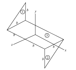
Figure-(1)
Write the expression for the area of the section 1 shown in the Figure-(1).
Here, the constant dimension is
Write the expression for the area of the section 2 shown in the Figure-(1).
Write the expression for the area of the section 3 shown in the Figure-(1).
Write the expression for the total area of the sheet.
Substitute
Write the expression of mass per unit area of the system.
Here, the mass of the sheet metal component is
Write the expression for the variation of the
Here, the coordinate of the considered point is
The below figure represent the schematic diagram of the elemental strip of section 1.
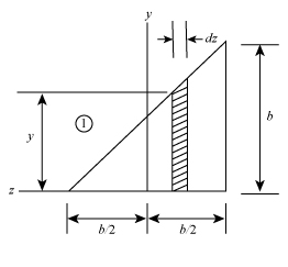
Figure-(2)
Write the expression for the distance of the centroid of the element from the
Write the expression for the mass of the elemental strip.
Here, the area of the elemental strip is
Write the expression for the moment of inertia of the element with respect to z- axis.
Write the expression for the moment of the inertia of the section 1.
Write the expression for the product of moment of inertia of the plane
Write the expression for the product of moment of inertia of the plane
Write the expression for the variation of the
The below figure represent the schematic diagram of the elemental strip of section 2.
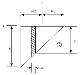
Figure-(3)
Write the expression for the mass of the elemental strip of section 2.
Write the expression for the moment of the inertia of the section 2.
Write the expression for the product of moment of inertia of the plane
Write the expression for the product of moment of inertia of the plane
Write the expression of mass per unit area of the section3 in Figure-(1).
Here, the mass of the rectangular sheet metal component is
Write the expression for the moment of the inertia of the section 3.
The product moment of the inertia for the plane
Write the expression for the moment of the inertia of the whole system.
Write the expression for the product of moment of inertia of the whole system.
Write the expression for the product of moment of inertia of the whole system.
Draw the diagram for the system to shows the action of forces on the system.
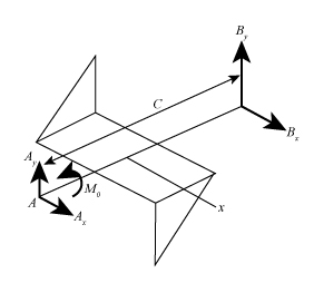
Figure-(4)
Here, the reaction on the point
Write the expression for the dynamic reaction at point
Write the expression for the dynamic reaction at point
Write the expression for the reaction forces along the y- direction.
Write the expression for the reaction forces along the x- direction.
Write the expression for the sum of the moment acting on the body along x -direction.
Here, distance between the point
Write the expression for the sum of the moment acting on the body along y -direction.
Calculation:
Substitute
Substitute
Substitute
Substitute
Substitute
Substitute
Substitute
Substitute
Substitute
Substitute
Substitute
Substitute
Substitute
Substitute
Substitute
Substitute
Substitute
Substitute
Substitute
Substitute
Substitute
Substitute
Substitute
Conclusion:
The dynamic reactions at
The dynamic reactions at
Want to see more full solutions like this?
Chapter 18 Solutions
Vector Mechanics For Engineers


- Problem (1) Gears A and B each have a mass of 4 kg and a radius of gyration of 75 mm about their centers, while gear C has a mass of 15 kg and a radius of gyration of 180 mm about its center. A couple moment M = (0.20) N-m is applied to gear C. Determine the number of revolutions gears A and B experience if gear C increases its angular velocity from 25 rpm to 500 rpm. B 80 mm S0 mm 200 mmarrow_forwardQ3. Two identical slender rods AB and BC are welded together to form an L-shaped assembly. The assembly is pressed against a spring at D and released from the position shown. Knowing that the maximum angle of rotation of the assembly in its subsequent motion is 90° counterclockwise, determine the magnitude of the angular velocity of the assembly as it passes through the position where rod AB forms an angle of 30° with the horizontal. h D B 1 0.4 m 0.4 marrow_forwardD C Answer: B 0.4 m- 0.4 m Two identical slender rods AB and BC are welded together to form an L-shaped assembly. The assembly is pressed against a spring at D and released from the position shown. Knowing that the maximum angle of rotation of the assembly in its subsequent motion is 58° with the horizontal (counterclockwise), determine the magnitude of the angular velocity of the assembly as it passes through the position where rod AB forms an angle of 27° with the horizontal.arrow_forward
- Gear A weighs 1 lb and has a radius of gyration of 1.3 in.; gear B weighs 6 lb and has a radius of gyration of 3 in.; gear C weighs 9 lb and has a radius of gyration of 4.3 in. Knowing a couple M of constant magnitude of 40 lb-in. is applied to gear A, determine (a) the angular acceleration of gear C, (b) the tangential force that gear B exerts on gear C. M A 2 in. 2 in. borg J 4 in. B 6 in. с w ណarrow_forwardIf the earth were a sphere, the gravitational attraction of the sun, moon, and planets would at all times be equivalent to a single force R acting at the mass center of the earth. However, the earth is actually an oblate spheroid and the gravitational system acting on the earth is equivalent to a force R and a couple M. Knowing that the effect of the couple M is to cause the axis of the earth to precess about the axis GA at the rate of one revolution in 25 800 years, determine the average magnitude of the couple M applied to the earth. Assume that the average density of the earth is 5.51 g/cm 3 , that the average radius of the earth is 6370 km, and that ( Note: This forced precession is known as the precession of the equinoxes and is not to be confused with the free precession discussed in Prob. 18.123.)arrow_forwardThe blade of a portable saw and the rotor of its motor have a total weight of 2.5 lb and a combined radius of gyration of 1.5 in. Knowing that the blade rotates as shown at the rate w1= 1500 rpm, determine the magnitude and direction of the couple M that a worker must exert on the handle of the saw to rotate it with a constant angular velocity w2= -(2.4 rad/s)j.arrow_forward
- The gear train shown consists of four gears of the same thickness and of the same material; two gears are of radius r, and the other two are of radius nr. The system is at rest when the couple M0 is applied to shaft C. Denoting by I0 the moment of inertia of a gear of radius r, determine the angular velocity of shaft A if the couple M0 is applied for one revolution of shaft C.arrow_forwardThe 9-kg rod AB, which length is 2.0-m, is pin connected at A and attached to a horizontal spring at B. The spring will always remain horizontal. k M 1. The rod is subjected at A to a couple M. The rod forms an angle 0-30° with the vertical when the spring, of stiffness 27 N.m, is unstretched. Determine the couple M required to the observe an angular velocity of the rod w=6 rad/s when 0 =51.arrow_forwardArm ACB rotates about Point Cwith an angular velocity of 39 radis counterclockwise. Two friction disks A and Bare pinned at their centers to arm ACB as shown. Know that the disks roll without slipping at the surfaces of contact. 2.4 in. 1.2 in. 0.9 in. 1.5 in. 0.6 in. D Determine the angular velocity of disk B. The angular velocity of disk B is radis . Determine the angular velocity of disk A. The angular velocity of disk A is [ rad/s O Determine the angular velocity of disk A. The angular velocity of disk A is rad/s O.arrow_forward
- Consider the mechanism shown. Members PQ and QR are joined by a hinge at Q. End P of member PQ is pin-supported and end R of member QR is constrained to move along a horizontal surface. Member PQ rotates clockwise at a constant rate of 12 rad/s. Member QR rotates counterclockwise at a rate of 3.84 rad/s. Which of the following gives the closest value to the magnitude of the angular acceleration of rod QR? 9.16, 6.18, 1.609, 35.2 rad/s^2?? Which of the following gives the closest value to the magnitude of the acceleration of point R? 3.13, 9.89, 10.28, 12.88 m/s^2??arrow_forwardA slender rod is bent to form a square frame of side 6 in. The frame is attached by a collar at A to a vertical shaft that rotates with a constant angular velocity w. Determine the value of w for which line AB forms an angle β = 48° with the horizontal axis.arrow_forwardEach of the gears A and B has a mass of 10 kg and a radius of gyration of 190 mm, while gear Chas a mass of 2.5 kg and a radius of gyration of 80 mm. Consider that a couple M of constant magnitude 10 N-m is applied to gear C. 250 mm 250 mm 100 mm Determine the corresponding tangential force acting on gear A. The corresponding tangential force acting on gear A is 26.35 O N.arrow_forward
 Elements Of ElectromagneticsMechanical EngineeringISBN:9780190698614Author:Sadiku, Matthew N. O.Publisher:Oxford University Press
 Mechanics of Materials (10th Edition)Mechanical EngineeringISBN:9780134319650Author:Russell C. HibbelerPublisher:PEARSON
 Thermodynamics: An Engineering ApproachMechanical EngineeringISBN:9781259822674Author:Yunus A. Cengel Dr., Michael A. BolesPublisher:McGraw-Hill Education
 Control Systems EngineeringMechanical EngineeringISBN:9781118170519Author:Norman S. NisePublisher:WILEY
 Mechanics of Materials (MindTap Course List)Mechanical EngineeringISBN:9781337093347Author:Barry J. Goodno, James M. GerePublisher:Cengage Learning
 Engineering Mechanics: StaticsMechanical EngineeringISBN:9781118807330Author:James L. Meriam, L. G. Kraige, J. N. BoltonPublisher:WILEY