
Concept explainers
Videos
A uniform slender rod AB of length L = 600 mm is placed with its center equidistant from two supports that are located at a distance b = 100 mm from each other. End B of the rod is raised a distance h0 = 80 mm and released; the rod then rocks on the supports as shown. Assuming that the impact at each support is perfectly plastic and that no slipping occurs between the rod and the supports, determine (a) the height h1 reached by end A after the first impact, (b) the height h2 reached by end B after the second impact.
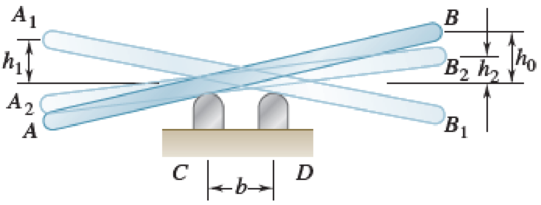
Fig. P17.117
Want to see the full answer?
Check out a sample textbook solution
Chapter 17 Solutions
VECTOR MECHANIC
Additional Engineering Textbook Solutions
Vector Mechanics For Engineers
Degarmo's Materials And Processes In Manufacturing
Manufacturing Engineering & Technology
Vector Mechanics for Engineers: Statics, 11th Edition
Introduction To Finite Element Analysis And Design
Statics and Mechanics of Materials


- A.The bar of negligible weight is supported by two springs, each having a stiffness k = 98 N/m. If the springs are originally unstretched, and the force is vertical as shown, determine the angle the bar makes with the horizontal, when the 31-N force is applied to the bar. B.Determine the stiffness k of each spring so that the 32-N force causes the bar to tip = 13.6° when the force is applied. Originally the bar is horizontal and the springs are unstretched. Neglect the weight of the bar.arrow_forwardThe assembly shown weighs 12 lb and consists of 4 thin 16-in.- diameter semicircular aluminum plates welded to a light 40-in.-long shaft AB. The assembly is at rest (w = 0) at time M0 is applied to it as shown, causing the assembly to complete one full revolution in 2 s. Determine (a) the couple (b) the dynamic reactions at A and B at T=0.arrow_forwardThe circular bar shown in the figure is vertical.fixed by the support at point A in the plane. AThe spring constant connected to the support is k = 40 N/m. Broadcastingundeformed length, arc between circle ABis the distance. C fitting (bracelet) with a mass of 200 grams,connected to the spring and move in a frictionless circle bar.can. When the union is θ = 30° from the rest positionis being released. In this case, relative to point B of the fittingthe highest height it can reach and the highestcalculate the speedarrow_forward
- Four identical rods, each of length = 1.3 m and weight 90 N, are connected at the frictionless pins A, B, C, and D. A compression spring of spring constant K = 5.3 N/mm connects pins B and C. and a weight W2 of 450 N is supported at pin D. The system is released from a configuration where = 45°. If the spring is not compressed at that configuration, show that the maximum de- flection of the weight We is 0.1966 m.arrow_forwardThe girl has a mass of 45 kg and center of mass at G. (Figure 1) Figure B 2m 0 30° 30° 1 of 1 Part A If she is swinging to a maximum height defined by 0 = 60°, determine the force developed along each of the four supporting posts such as AB at the instant 0 = 0°. The swing is centrally located between the posts. Express your answer to three significant figures and include the appropriate units. F = Submit μА Value Provide Feedback N Previous Answers Request Answer ? X Incorrect; Try Again; 5 attempts remaining Next >arrow_forwardEnd B of the uniform 2.7-kg bar AB is connected to a small roller that moves in a horizontal slot. The other end of the bar is pinned to the homogeneous 1.8-kg disk that rolls without slipping on the vertical surface. The spring attached to A has a free length of 0.3 m and a stiffness of 58 N/m. After the system is becomes horizontal. Determine the magnitude of the force P that acts on the bar at B. 2.1 m 0.24 m 0.9 m www 1.8 kg 1.5 m 2.7 kg Parrow_forward
- Question 2: A 35-kg disk rests on an inclined surface for which us=0.2µus=0.2. Determine the maximum vertical force P that may be applied to bar AB without causing the disk to slip at C. Neglect the mass of the bar. 200 mm 300 mm -600 mm- B 200 mm 30 P.arrow_forwardEngineering mechanics – statics 1$t stage Lecturer: Amany Barrak :- Example : The floor crane and the driver have a total weight of 2500 Ib with a center of gravity at G. If the crane is required to the 500-lb drum, determine the normal reaction on both the wheels at A and both the wheels at B when the boom is in the position shown. 12 i 3 ft 30 6 ft 8.4 ft 2.2 ft 1.4 ftarrow_forwardA 81-lb sheet of plywood rests on two small wooden blocks as shown. It is allowed to lean 20° from the vertical under the action of a force P which is perpendicular to the sheet. Friction at all surfaces of blocks A and B is sufficient to prevent slipping. Determine the magnitude P and the vertical reaction forces at A and B. D 4.0' 1.0' E A 5.2' DE = 3.3 ft 1.8' B 1 -20⁰arrow_forward
- The hoist consists of a single rope and an arrangement of frictionless pulleys as shown. If the angle 0 = 33°, determine the force that must be applied to the rope, Frope, to lift a load of 4.7 kN. The three- pulley and hook assembly at the center of the system has a mass of 28.5 kg with a center of mass that lies on the line of action of the force applied to the hook. cc 130 BY NC SA 2013 Michael Swanbom Note the figure may not be to scale. Frope KN B A Fhook Fropearrow_forwardWhen the 0.05-kg body is in the position shown, the linear spring is stretched 15 mm. Determine the force P required to break contact at C. Complete solutions for (a) including the effects of the weight and (b) neglecting the weight. P56 mm A k = 1900 N/m B 56 mm Answers: (a) Including the weight, P = i N (b) Neglecting the weight, P = 32 mm 32 mmarrow_forward*********MASS IS 10 KG, NOT LBS********** The 10 kg slender bar AB, shown in the figure, has a length of 2 m. A blockof negligible mass, pinned freely to end A, is confined to move along the smooth circular groove with its centre at O. End B rests on the floor for which the coefficient of kinetic friction, µk = 0.4. If the bar is released from rest when θ = 30 degrees *********MASS IS 10 KG, NOT LBS********** a)draw the free body, kinematic and kinetic diagrams for the bar, b) set up a global reference axes system, and write down the relevantkinetic and kinematic relationships with respect to reference axes system, and c) determine the angular acceleration of the bar and the reaction forces at ends A and B. *********MASS IS 10 KG, NOT LBS**********arrow_forward
 Elements Of ElectromagneticsMechanical EngineeringISBN:9780190698614Author:Sadiku, Matthew N. O.Publisher:Oxford University Press
 Mechanics of Materials (10th Edition)Mechanical EngineeringISBN:9780134319650Author:Russell C. HibbelerPublisher:PEARSON
 Thermodynamics: An Engineering ApproachMechanical EngineeringISBN:9781259822674Author:Yunus A. Cengel Dr., Michael A. BolesPublisher:McGraw-Hill Education
 Control Systems EngineeringMechanical EngineeringISBN:9781118170519Author:Norman S. NisePublisher:WILEY
 Mechanics of Materials (MindTap Course List)Mechanical EngineeringISBN:9781337093347Author:Barry J. Goodno, James M. GerePublisher:Cengage Learning
 Engineering Mechanics: StaticsMechanical EngineeringISBN:9781118807330Author:James L. Meriam, L. G. Kraige, J. N. BoltonPublisher:WILEY