Concept explainers
Solve Prob. 16.137 when θ = 90°.
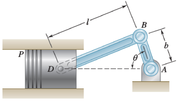
16.137 In the engine system shown, l = 250 mm and b = 100 mm. The connecting rod BD is assumed to be a 1.2-kg uniform slender rod and is attached to the 1.8-kg piston P. During a test of the system, crank AB is made to rotate with a constant angular velocity of 600 rpm clockwise with no force applied to the face of the piston. Determine the forces exerted on the connecting rod at B and D when θ = 180°. (Neglect the effect of the weight of the rod.)

Fig. P16.137
The forces exerted on the connecting rod at B and D when
Answer to Problem 16.138P
The forces exerted on the connecting rod at B is
The forces exerted on the connecting rod at D is
Explanation of Solution
Given information:
The length of the rod BD is
The length of the rod AB is
The mass of the rod BD is
The mass of the piston P is
The angular velocity of AB is
Calculation:
Consider the acceleration due to gravity
Calculate the angular velocity in
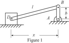
Sketch the Free body Diagram of the system as shown in Figure 1.

Refer to Figure 1.
Calculate the distance
Substitute
Calculate the position vectors as shown below.
Position of B with respect to A.
Position of D with respect to B.
Position of mass center G with respect to D.
Calculate the velocity at B
Substitute
Calculate the velocity at D
Substitute
Resolving the i and j components as shown below.
For j component.
For i component.
Substitute
Consider that the angular acceleration as
Calculate the acceleration at B
Substitute
Calculate the acceleration
Substitute
Resolving i and j components as shown below.
For j component.
For i component.
Substitute
Calculate the acceleration of mass center G of bar BD
Substitute
Resolving the components as shown below.
Calculate the mass moment of inertia for BD
Substitute
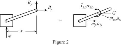
Sketch the Free Body Diagram of the piston with the bar BD as shown in Figure 2.

Refer to Figure 2.
Apply the Equilibrium of forces along x direction as shown below.
Substitute
Apply the Equilibrium of moment about B as shown below.
Substitute
Apply the Equilibrium of forces along y direction as shown below.
Substitute
Calculate the force acting at B as shown below.
Substitute
Hence, the forces exerted on the connecting rod at B is
Sketch the Free Body Diagram of the piston as shown in Figure 3.

Refer to Figure 3.
Calculate the force acting on the rod at D as shown below.
Substitute
Calculate the magnitude of force at D as shown below.
Therefore, the forces exerted on the connecting rod at D is
Want to see more full solutions like this?
Chapter 16 Solutions
Vector Mechanics for Engineers: Statics and Dynamics
Additional Engineering Textbook Solutions
Vector Mechanics For Engineers
Mechanics of Materials (10th Edition)
Thermodynamics: An Engineering Approach
Automotive Technology: Principles, Diagnosis, And Service (6th Edition) (halderman Automotive Series)
Web Development and Design Foundations with HTML5 (8th Edition)
Electric Circuits. (11th Edition)
- can you explain how in a coordinate frame transformation: v = {v_n}^T {n-hat} and then it was found that {n-hat} = [C]^T {b-hat} so v_n = {v_n}^T [C]^T {b-hat}, how does that equation go from that to this --> v_n = [C]^T v_barrow_forward6) If (k = 0,7 cm) find Imax for figure below. 225mm 100mm ثلاثاء. 100mm 150mm 75mm Ans: Tmax=45:27 N/cm F-400 Narrow_forwardThe man has a weight W and stands halfway along the beam. The beam is not smooth, but the planes at A and B are smooth (and plane A is horizontal). Determine the magnitude of the tension in the cord in terms of W and θ.arrow_forward
- A 15 cm-OD pipe is buried with its centerline 1.25 m below the surface of the ground [k of soil is 0.35 W/(m K)]. An oil having a density of 800 kg/m³ and a specific heat of 2.1 kJ/(kg K) flows in the pipe at 5.6 L/s. Assuming a ground surface temperature of 5°C and a pipe wall temperature of 95°C, estimate the length of pipe in which the oil temperature decreases by 5.5°C. + Tε = 5ºC Z= 1.25 m D= 15 cm 7p=95°Carrow_forwardFind the solution of the following Differential Equations 1) 4y+y=0, y(0)=2, y'(0) = 0. 2) y+y=0, y(0) = A, y'(0) = B. 3) "+2y'-8y=0, y(0)=1, y'(0)=8. 4) y"-2y-3y=0, y(0)=1, y'(0)=7. 5) y"-ky' =0, y(0)=2, y'(0) =k. 6) y+ky'-2k2y=0, y(0)=2, y'(0) = 2k. 7) y'+4y=0, y(0)=2.8 y+y-17sin(21) y(0)=-1. 9) y-y'-6y=0, y(0)=6. y'(0)=13. 10) y-y=0, 11) y"-4y+4y=0, y(0)=4, y'(0) = 0. y(0) = 2.1, y'(0)=3.9 12) y+2y+2y=0, y(0)=1, y'(0)=-3. 13) "+7y+12y=21e", y(0)=3.5, y'(0)=-10. 14) "+9y=10e", y(0)=0. y'(0) = 0. 15) y+3y+2.25y=91³ +64. y(0)=1, y'(0) = 31.5 16) "-6y+5y= 29 cos(21), y(0)=3.2, y'(0) = 6.2 17) y+2y+2y=0, y(0)=0, y'(0)=1. 18) y+2y+17y=0, y(0)=0, y'(0)=12. 19) y-4y+5y=0, y(0)-1, y'(0) 2. 20) 9y-6y+y=0. y(0)=3, y'(0)=1. 21) -2y+10y=0, y(0)=3, y'(0)=3. 22) 4y-4y+37y=0, (0) 3. y(0) 1.5 23) 4y-8y+5y=0, (0)-0, y(0) 1. 24) y+y+1.25y=0, y(0) 1. y'(0) -0.5 25) y+y=2 cos(1). y(0) 2. y'(0) = 0. 26) -4y+3y=0, (0)-3, y'(0) = 7. 27) y+2y+y=e", y(0)-0. y'(0) = 0. 29) 28) y+2y-3y-10sinh(2),…arrow_forwardNote: Please provide a clear, step-by-step simplified handwritten working out (no explanations!), ensuring it is done without any AI involvement. I require an expert-level answer, and I will assess and rate based on the quality and accuracy of your work and refer to the provided image for more clarity. Make sure to double-check everything for correctness before submitting appreciate your time and effort!. Question:arrow_forward
- 4. Block A and B are two different pieces of wood. Determine the minimum dimension for "a", if the shear stress of the wood is 50Mpa. The thickness of the wood is 30cm. 600N Aarrow_forward1. Determine the reaction force at A. 60 kN 5 B 1 m 1 m- -1 m 4 3 m 30 kN marrow_forwardFind the Laplace Transform of the following functions 1) f() cos(ar) Ans. F(s)=7 2ws 2) f() sin(at) Ans. F(s)= s² + a² 3) f(r)-rcosh(at) Ans. F(s)= 2as 4)(t)=sin(at) Ans. F(s)= 2 5) f(1) = 2te' Ans. F(s)= (S-1) 5+2 6) (1) e cos() Ans. F(s) = (+2)+1 7) (1) (Acostẞr)+ Bsin(Br)) Ans. F(s)- A(s+a)+BB (s+a)+B 8) f()-(-)() Ans. F(s)= 9)(1)(1) Ans. F(s): 10) f(r),()sin() Ans. F(s): 11) 2 k 12) 0 13) 0 70 ㄷ.. a 2a 3a 4a 2 3 4 14) f(1)=1, 0<1<2 15) (1) Ksin(t) 0arrow_forwardarrow_back_iosSEE MORE QUESTIONSarrow_forward_ios
 Elements Of ElectromagneticsMechanical EngineeringISBN:9780190698614Author:Sadiku, Matthew N. O.Publisher:Oxford University Press
 Mechanics of Materials (10th Edition)Mechanical EngineeringISBN:9780134319650Author:Russell C. HibbelerPublisher:PEARSON
 Thermodynamics: An Engineering ApproachMechanical EngineeringISBN:9781259822674Author:Yunus A. Cengel Dr., Michael A. BolesPublisher:McGraw-Hill Education
 Control Systems EngineeringMechanical EngineeringISBN:9781118170519Author:Norman S. NisePublisher:WILEY
 Mechanics of Materials (MindTap Course List)Mechanical EngineeringISBN:9781337093347Author:Barry J. Goodno, James M. GerePublisher:Cengage Learning
 Engineering Mechanics: StaticsMechanical EngineeringISBN:9781118807330Author:James L. Meriam, L. G. Kraige, J. N. BoltonPublisher:WILEY


