
Vector Mechanics For Engineers
12th Edition
ISBN: 9781259977237
Author: BEER
Publisher: MCG
expand_more
expand_more
format_list_bulleted
Concept explainers
Videos
Textbook Question
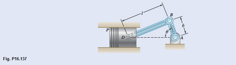
Chapter 16.2, Problem 16.137P
In the engine system shown,
Expert Solution & Answer
Want to see the full answer?
Check out a sample textbook solution
Students have asked these similar questions
Gear A has a mass of 1 kg and a radius of gyration of 30 mm; gear B has a mass of 4 kg and a radius of gyration of 75 mm; gear C has a mass of 9 kg and a radius of gyration of 100 mm. The system is at rest when a couple M0 of constant magnitude 4 N.m is applied to gear C . Assuming that no slipping occurs between the gears, determine the number of revolutions required for disk A to reach an angular velocity of 300 rpm.
3. The connecting rod of the steam engine shown schematically is assumed to be a slender uniform
rod. 4 ft long weighing 322 Ib. the crank AO is 1ft long and rotates at a constant rate of 10 rad/s.
the force on the 64.4 Ib cross-head at the given instant is 2142 Ib. neglecting friction. Determine
the normal force on the crosshead and the horizontal and vertical components at crank pin
force at A.
А
45deg
В
The parallelogram linkage shown moves in the vertical plane with the uniform 9.3-kg bar EF attached to the plate at E by a pin which
is welded both to the plate and to the bar. A torque (not shown) is applied to link AB through its lower pin to drive the links in a
clockwise direction. When e reaches 51°, the links have an angular acceleration and an angular velocity of 7.0 rad/s² and 2.3 rad/s,
respectively. For this instant calculate the magnitudes of the force F and torque M supported by the pin at E.
Welded
1435 mm
pin
F
995
995
mm
mm
B
D
Horizontal
Answers:
F =
i
N
M =
i
N•m
Chapter 16 Solutions
Vector Mechanics For Engineers
Ch. 16.1 - Two pendulums, A and B, with the masses and...Ch. 16.1 - Two pendulums, A and B, with the masses and...Ch. 16.1 - Two solid cylinders, A and B, have the same mass m...Ch. 16.1 - A 6-ft board is placed in a truck with one end...Ch. 16.1 - Prob. 16.F2PCh. 16.1 - Two uniform disks and two cylinders are assembled...Ch. 16.1 - Prob. 16.F4PCh. 16.1 - A 60-Ib uniform thin panel is placed in a truck...Ch. 16.1 - A 60-lb uniform thin panel is placed in a truck...Ch. 16.1 - Knowing that the coefficient of static friction...
Ch. 16.1 - Prob. 16.4PCh. 16.1 - A uniform rod BC of mass 4 kg is connected to a...Ch. 16.1 - A 2000-kg truck is being used to lift a 400-kg...Ch. 16.1 - The support bracket shown is used to transport a...Ch. 16.1 - Prob. 16.8PCh. 16.1 - A 20-kg cabinet is mounted on casters that allow...Ch. 16.1 - Prob. 16.10PCh. 16.1 - A completely filled barrel and its contents have a...Ch. 16.1 - A 40-kg vase has a 200-mm-diameter base and is...Ch. 16.1 - Prob. 16.13PCh. 16.1 - Bars AB and BE, each with a mass of 4 kg, are...Ch. 16.1 - At the instant shown, the tensions in the vertical...Ch. 16.1 - Three bars, each of mass 3 kg, are welded together...Ch. 16.1 - Prob. 16.17PCh. 16.1 - Prob. 16.18PCh. 16.1 - Prob. 16.19PCh. 16.1 - The coefficients of friction between the 30-lb...Ch. 16.1 - Prob. 16.21PCh. 16.1 - Prob. 16.22PCh. 16.1 - Prob. 16.23PCh. 16.1 - Prob. 16.24PCh. 16.1 - Prob. 16.25PCh. 16.1 - Prob. 16.26PCh. 16.1 - Prob. 16.27PCh. 16.1 - Solve Prob. 16.27, assuming that the initial...Ch. 16.1 - The 100-mm-radius brake drum is attached to a...Ch. 16.1 - The 180-mm-radius disk is at rest when it is...Ch. 16.1 - Solve Prob. 16.30, assuming that the direction of...Ch. 16.1 - In order to determine the mass moment of inertia...Ch. 16.1 - Prob. 16.33PCh. 16.1 - Each of the double pulleys shown has a mass moment...Ch. 16.1 - Prob. 16.35PCh. 16.1 - Solve Prob. 16.35, assuming that the couple M is...Ch. 16.1 - Gear A weighs 1 lb and has a radius of gyration of...Ch. 16.1 - The 25-lb double pulley shown is at rest and in...Ch. 16.1 - A belt of negligible mass passes between cylinders...Ch. 16.1 - Solve Prob. 16.39 for P=2.00lb .Ch. 16.1 - Disk A has a mass of 6 kg and an initial angular...Ch. 16.1 - Prob. 16.42PCh. 16.1 - Prob. 16.43PCh. 16.1 - Disk B is at rest when it is brought into contact...Ch. 16.1 - Cylinder A has an initial angular velocity of 720...Ch. 16.1 - Prob. 16.46PCh. 16.1 - Prob. 16.47PCh. 16.1 - Prob. 16.48PCh. 16.1 - (a) In Prob. 16.48, determine the point of the rod...Ch. 16.1 - A force P with a magnitude of 3 N is applied to a...Ch. 16.1 - Prob. 16.51PCh. 16.1 - A 250-lb satellite has a radius of gyration of 24...Ch. 16.1 - Prob. 16.53PCh. 16.1 - A uniform semicircular plate with a mass of 6 kg...Ch. 16.1 - Prob. 16.55PCh. 16.1 - Prob. 16.56PCh. 16.1 - The 12-lb uniform disk shown has a radius of r=3.2...Ch. 16.1 - Prob. 16.58PCh. 16.1 - Prob. 16.59PCh. 16.1 - Prob. 16.60PCh. 16.1 - The 400-lb crate shown is lowered by means of two...Ch. 16.1 - Prob. 16.62PCh. 16.1 - Prob. 16.63PCh. 16.1 - A beam AB with a mass m and of uniform...Ch. 16.1 - Prob. 16.65PCh. 16.1 - Prob. 16.66PCh. 16.1 - Prob. 16.67PCh. 16.1 - Prob. 16.68PCh. 16.1 - Prob. 16.69PCh. 16.1 - Solve Prob. 16.69, assuming that the sphere is...Ch. 16.1 - A bowler projects an 8-in.-diameter ball weighing...Ch. 16.1 - Solve Prob. 16.71, assuming that the bowler...Ch. 16.1 - A uniform sphere of radius r and mass m is placed...Ch. 16.1 - A sphere of radius r and mass m has a linear...Ch. 16.2 - A cord is attached to a spool when a force P is...Ch. 16.2 - A cord is attached to a spool when a force P is...Ch. 16.2 - A front-wheel-drive car starts from rest and...Ch. 16.2 - A front-wheel-drive car starts from rest and...Ch. 16.2 - Prob. 16.F5PCh. 16.2 - Prob. 16.F6PCh. 16.2 - Prob. 16.F7PCh. 16.2 - Prob. 16.F8PCh. 16.2 - Show that the couple I of Fig. 16.15 can be...Ch. 16.2 - Prob. 16.76PCh. 16.2 - Prob. 16.77PCh. 16.2 - A uniform slender rod of length L=36 in. and...Ch. 16.2 - Prob. 16.79PCh. 16.2 - Prob. 16.80PCh. 16.2 - Prob. 16.81PCh. 16.2 - Prob. 16.82PCh. 16.2 - Prob. 16.83PCh. 16.2 - A uniform rod of length L and mass m is supported...Ch. 16.2 - Prob. 16.85PCh. 16.2 - Prob. 16.86PCh. 16.2 - Prob. 16.87PCh. 16.2 - Two identical 4-lb slender rods AB and BC are...Ch. 16.2 - Prob. 16.89PCh. 16.2 - Prob. 16.90PCh. 16.2 - Prob. 16.91PCh. 16.2 - Prob. 16.92PCh. 16.2 - Prob. 16.93PCh. 16.2 - Prob. 16.94PCh. 16.2 - A homogeneous sphere S, a uniform cylinder C, and...Ch. 16.2 - Prob. 16.96PCh. 16.2 - Prob. 16.97PCh. 16.2 - Prob. 16.98PCh. 16.2 - Prob. 16.99PCh. 16.2 - A drum of 80-mm radius is attached to a disk of...Ch. 16.2 - Prob. 16.101PCh. 16.2 - Prob. 16.102PCh. 16.2 - Prob. 16.103PCh. 16.2 - Prob. 16.104PCh. 16.2 - Prob. 16.105PCh. 16.2 - A 12-in.-radius cylinder of weight 16 lb rests on...Ch. 16.2 - A 12-in.-radius cylinder of weight 16 lb rests on...Ch. 16.2 - Gear C has a mass of 5 kg and a centroidal radius...Ch. 16.2 - Two uniform disks A and B, each with a mass of 2...Ch. 16.2 - Prob. 16.110PCh. 16.2 - Prob. 16.111PCh. 16.2 - Prob. 16.112PCh. 16.2 - Prob. 16.113PCh. 16.2 - A small clamp of mass mBis attached at B to a hoop...Ch. 16.2 - Prob. 16.115PCh. 16.2 - A 4-lb bar is attached to a 10-lb uniform cylinder...Ch. 16.2 - The uniform rod AB with a mass m and a length of...Ch. 16.2 - Prob. 16.118PCh. 16.2 - A 40-lb ladder rests against a wall when the...Ch. 16.2 - A beam AB of length L and mass m is supported by...Ch. 16.2 - End A of the 6-kg uniform rod AB rests on the...Ch. 16.2 - Prob. 16.122PCh. 16.2 - Prob. 16.123PCh. 16.2 - The 4-kg uniform rod ABD is attached to the crank...Ch. 16.2 - The 3-lb uniform rod BD is connected to crank AB...Ch. 16.2 - Prob. 16.126PCh. 16.2 - Prob. 16.127PCh. 16.2 - Prob. 16.128PCh. 16.2 - Prob. 16.129PCh. 16.2 - Prob. 16.130PCh. 16.2 - Prob. 16.131PCh. 16.2 - Prob. 16.132PCh. 16.2 - Prob. 16.133PCh. 16.2 - Prob. 16.134PCh. 16.2 - Prob. 16.135PCh. 16.2 - The 6-kg rod BC connects a 10-kg disk centered at...Ch. 16.2 - In the engine system shown, l=250 mm and b=100 mm....Ch. 16.2 - Solve Prob. 16.137 when =90 .Ch. 16.2 - The 4-lb uniform slender rod AB, the 8-lb uniform...Ch. 16.2 - Prob. 16.140PCh. 16.2 - Two rotating rods in the vertical plane are...Ch. 16.2 - Prob. 16.142PCh. 16.2 - Prob. 16.143PCh. 16.2 - Prob. 16.144PCh. 16.2 - Prob. 16.145PCh. 16.2 - Prob. 16.146PCh. 16.2 - Prob. 16.147PCh. 16.2 - Prob. 16.148PCh. 16.2 - Prob. 16.149PCh. 16.2 - Prob. 16.150PCh. 16.2 - (a) Determine the magnitude and the location of...Ch. 16.2 - Draw the shear and bending-moment diagrams for the...Ch. 16 - A cyclist is riding a bicycle at a speed of 20 mph...Ch. 16 - Prob. 16.154RPCh. 16 - The total mass of the Baja car and driver,...Ch. 16 - Prob. 16.156RPCh. 16 - Prob. 16.157RPCh. 16 - Prob. 16.158RPCh. 16 - A bar of mass m=5 kg is held as shown between four...Ch. 16 - A uniform plate of mass m is suspended in each of...Ch. 16 - Prob. 16.161RPCh. 16 - Two 3-kg uniform bars are connected to form the...Ch. 16 - Prob. 16.163RPCh. 16 - Prob. 16.164RP
Knowledge Booster


Learn more about
Need a deep-dive on the concept behind this application? Look no further. Learn more about this topic, mechanical-engineering and related others by exploring similar questions and additional content below.Similar questions
- When the 18-kg wheel shown is attached to a balancing machine and made to spin at a rate of 12.5 rev/s, it is found that the forces exerted by the wheel on the machine are equivalent to a force-couple system consisting of a force F = (160 N)j applied at and a couple where the unit vectors form a triad that rotates with the wheel. (a ) Determine the distance from the axis of rotation to the mass center of the wheel and the products of inertia Ixy and Ixz (b) If only two corrective masses are to be used to balance the wheel statically and dynamically, what should these masses be and at which of the points A, B, D or E, should they be placed?arrow_forwardA shaft carries four masses A, B, C and D of magnitude 10 kg, 20 kg, 15 kg and 25 kg respectively and revolving at radii 100 mm, 50 mm, 80 mm and 120mm in planes measured from A at 100 mm, 300 mm and 500 mm. The angles between the cranks measured anticlockwise are A to B = 40°, B to C = 50° and C to D = 150°. The balancing masses are to be placed in planes X and Y. The distance between the planes A and X is 50 mm, between X and Y is 350 mm. If the balancing masses revolve at a radius of 50 mm, find the magnitude for mass on plane X (consider plane X as the refernce plane).arrow_forwardA shaft carries four masses A, B, C and D of magnitude 10 kg, 20 kg, 15 kg and 25 kg respectively and revolving at radii 100 mm, 50mm, 80 mm and 120mm in planes measured from A at 100 mm, 300 mm and 500 mm.The angles between the cranks measured anticlockwise are A to B = 40°, B to C = 50° and C to D = 150°.The balancing masses are to be placed in planes X and Y. The distance between the planes A and X is 50 mm, between X and Y is 350mm.If the balancing masses revolve at a radius of 50 mm, find the magnitude for mass on plane X (consider plane X as the refernce plane).Select one:A.78.8 kgB.68.8 kgC.98.8 kgD.48.8 kg For the data given in Question 4, find the magnitude for mass on plane Y (consider plane X as the reference plane).Select one:A.59.1 kgB.69.1 kgC.99.1 kg D.49.1 kgarrow_forward
- The 10-oz disk shown spins at the rate w1 = 750 rpm, while axle AB rotates as shown with an angular velocity w2. Determine the maximum allowable magnitude of w2 if the dynamic reactions at A and B are not to exceed 0.25 lb each.arrow_forwardProblem (1) Gears A and B each have a mass of 4 kg and a radius of gyration of 75 mm about their centers, while gear C has a mass of 15 kg and a radius of gyration of 180 mm about its center. A couple moment M = (0.20) N-m is applied to gear C. Determine the number of revolutions gears A and B experience if gear C increases its angular velocity from 25 rpm to 500 rpm. B 80 mm S0 mm 200 mmarrow_forwardIn the helicopter shown; a vertical tail propeller is used to pre- vent rotation of the cab as the speed of the main blades is changed. Assuming that the tail propeller is not operating determine the final angular velocity of the cab after the speed of the main blades has been changed from I80 to 240 rpm. (The speed of the main blades is measured relative to the cab, and the cab has a centroidal moment of inertia of 650 lb.ft.s2. Each of the four main blades is assumed to be a slender rod 14 ft weighing 55 lb.)arrow_forward
- Give me right solution with clear calculationsarrow_forwardConsider the mechanism shown. Members PQ and QR are joined by a hinge at Q. End P of member PQ is pin-supported and end R of member QR is constrained to move along a horizontal surface. Member PQ rotates clockwise at a constant rate of 12 rad/s. Member QR rotates counterclockwise at a rate of 3.84 rad/s. Which of the following gives the closest value to the magnitude of the angular acceleration of rod QR? 9.16, 6.18, 1.609, 35.2 rad/s^2?? Which of the following gives the closest value to the magnitude of the acceleration of point R? 3.13, 9.89, 10.28, 12.88 m/s^2??arrow_forwardNeed help.arrow_forward
- The cranks and connecting rods of a four cylinder in-line engine running at 2000 rpm are 60mm and 240mm each respectively. The cylinders are spaced 150 mm apart. If the cylinders are numbered 1 to 4 in sequence from one end, the cranks appear at intervals of 90º in an end view in the order 1-4-2-3.The reciprocating mass for each cylinder is 15 kg. Determine (i) unbalanced primary and secondary forces, (ii) unbalanced primary and secondary couples with reference to central plane of the enginearrow_forwardThe reciprocating masses of the first three cylinders of a four cylinder engine are 4.1, 6.2 and 7.4 tonnes respectively. The centre lines of the three cylinders are 5.2 m, 3.2 m and 1.2 m from the fourth cylinder. If the cranks for all the cylinders are equal, determine the reciprocating mass of the fourth cylinder and the angular position of the cranks such that the system is completely balanced for the primary force and couple. If the cranks are 0.8 m long, the connecting rods 3.8 m, and the speed of the engine 75 r.p.m. ; find the maximum unbalanced secondary force and the crank angle at which it occurs. solve graphicallyarrow_forwardPlease do all the blanks on the pic.arrow_forward
arrow_back_ios
SEE MORE QUESTIONS
arrow_forward_ios
Recommended textbooks for you
 Elements Of ElectromagneticsMechanical EngineeringISBN:9780190698614Author:Sadiku, Matthew N. O.Publisher:Oxford University Press
 Mechanics of Materials (10th Edition)Mechanical EngineeringISBN:9780134319650Author:Russell C. HibbelerPublisher:PEARSON
 Thermodynamics: An Engineering ApproachMechanical EngineeringISBN:9781259822674Author:Yunus A. Cengel Dr., Michael A. BolesPublisher:McGraw-Hill Education
 Control Systems EngineeringMechanical EngineeringISBN:9781118170519Author:Norman S. NisePublisher:WILEY
 Mechanics of Materials (MindTap Course List)Mechanical EngineeringISBN:9781337093347Author:Barry J. Goodno, James M. GerePublisher:Cengage Learning
 Engineering Mechanics: StaticsMechanical EngineeringISBN:9781118807330Author:James L. Meriam, L. G. Kraige, J. N. BoltonPublisher:WILEY
Elements Of Electromagnetics
Mechanical Engineering
ISBN:9780190698614
Author:Sadiku, Matthew N. O.
Publisher:Oxford University Press
Mechanics of Materials (10th Edition)
Mechanical Engineering
ISBN:9780134319650
Author:Russell C. Hibbeler
Publisher:PEARSON
Thermodynamics: An Engineering Approach
Mechanical Engineering
ISBN:9781259822674
Author:Yunus A. Cengel Dr., Michael A. Boles
Publisher:McGraw-Hill Education
Control Systems Engineering
Mechanical Engineering
ISBN:9781118170519
Author:Norman S. Nise
Publisher:WILEY
Mechanics of Materials (MindTap Course List)
Mechanical Engineering
ISBN:9781337093347
Author:Barry J. Goodno, James M. Gere
Publisher:Cengage Learning
Engineering Mechanics: Statics
Mechanical Engineering
ISBN:9781118807330
Author:James L. Meriam, L. G. Kraige, J. N. Bolton
Publisher:WILEY
Mechanical Design (Machine Design) Clutches, Brakes and Flywheels Intro (S20 ME470 Class 15); Author: Professor Ted Diehl;https://www.youtube.com/watch?v=eMvbePrsT34;License: Standard Youtube License