
Concept explainers
Videos
A hemisphere of weight W and radius r is released from rest in the position shown. Determine (a) the minimum value of μs for which the hemisphere starts to roll without sliding, (b) the corresponding acceleration of point B. (Hint: Note that
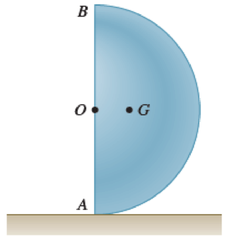
Fig. P16.111
Want to see the full answer?
Check out a sample textbook solution
Chapter 16 Solutions
Vector Mechanics for Engineers: Statics and Dynamics
Additional Engineering Textbook Solutions
Fundamentals Of Thermodynamics
Engineering Mechanics: Dynamics (14th Edition)
Manufacturing Engineering & Technology
Introduction To Finite Element Analysis And Design
Degarmo's Materials And Processes In Manufacturing
Shigley's Mechanical Engineering Design (McGraw-Hill Series in Mechanical Engineering)


- Problem #5) A pulley having a moment of inertia of 0.191b-ft-s² is connected to two masses as shown. The masses A and B have linear acceleration of 1.85ft/s² upward and 1.11 ft/s² downward, respectively. Assuming no axle friction, determine (a) the tension forces TA and TB in the cables connecting the masses, and (b) the angular acceleration a of the pulley. 6 in. Include and present the Free Body Diagram and Inertial Response Diagram as part of the solving process. Hint #1: Hint #2: use mA = 0.1553slugs, and mB = 0.3106slugs treat each body separately B 10 lb 10 in. A 5 lbarrow_forwardTwo uniform cylinders, each of mass m = 6 kg and radius r = 125 mm, are connected by a belt as shown. Knowing that at the instant shown the angular velocity of cylinder A is 30 rad/s counterclockwise, determine (a) the time required for the angular velocity of cylinder A to be reduced to 5 rad/s, (b) the tension in the portion of belt connecting the two cylinders.arrow_forwardThe 10-in.-radius brake drum is attached to a larger flywheel which is not shown. The total mass moment of inertia of the flywheel and drum is 22 lb ⋅ ft ⋅ s 2 and the coefficient of kinetic friction between the drum and the brake shoe is 0.41. Knowing that the initial angular velocity is 255 rpm clockwise, determine the force which must be exerted by the hydraulic cylinder at point B if the system is to stop in 85 revolutions.arrow_forward
- The 10-in.-radius brake drum is attached to a larger flywheel which is not shown. The total mass moment of inertia of the flywheel and drum is 22 lb ⋅ ft ⋅ s 2 and the coefficient of kinetic friction between the drum and the brake shoe is 0.41. Knowing that the initial angular velocity is 255 rpm clockwise, determine the force which must be exerted by the hydraulic cylinder at point B if the system is to stop in 85 revolutions. DO NOT ROUND OFF IN THE SOLUTION. ROUND OFF ONLY THE FINAL ANSWERarrow_forwardRequired information NOTE: This is a multi-part question. Once an answer is submitted, you will be unable to return to this part. A 4-kg slender rod is welded to the edge of a 3-kg uniform disk as shown. The assembly rotates about A in a vertical plane under the combined effect of gravity and of the vertical force P. Know that at the instant shown, the assembly has an angular velocity of 12 rad/s and an angular acceleration of 36.5 rad/s2, both counterclockwise. 120 mm Determine the force P. B The force P is D 240 mm с 240 mm (You must provide an answer before moving on to the next part.) |N.↓arrow_forwardTwo uniform cylinders, each of weight W = 14 lb and radius r = 5 in., are connected by a belt as shown. Knowing that at the instant shown the angular velocity of cylinder B is 30 rad/s clockwise, determine (a) the distance through which cylinder A will rise before the angular velocity of cylinder B is reduced to 5 rad/s, (b ) the tension in the portion of belt connecting the two cylinders.arrow_forward
- The rotor of an electric motor has an angular velocity of 3520 rpm when the load and power are cut off. The 110-lb rotor, which has a centroidal radius of gyration of 9 in., then coasts to rest. Knowing that the kinetic friction of the rotor produces a couple of magnitude 2.5 lb-ft, determine the number of revolutions that the rotor executes before coming to rest. The number of revolutions that the rotor executes before coming to rest is rev.arrow_forwardThe mechanism shown is one of two identical mechanisms attached to the two sides of a 180-lb uniform rectangular door. Edge ABC of the door is guided by wheels of negligible mass that roll in horizontal and vertical tracks. A spring of constant k is attached to wheel Bin such a way that its tension is zero when 0 = 30°. Knowing that the door is released from rest in the position 0 = 45° and reaches the vertical position with an angular velocity of 0.6 rad/s, determine the spring constant k. 5 ft 5 ft The spring constant is Ib/ft.arrow_forwardGear A weighs 1 lb and has a radius of gyration of 1.3 in.; gear B weighs 6 lb and has a radius of gyration of 3 in.; gear C weighs 9 lb and has a radius of gyration of 4.3 in. Knowing a couple M of constant magnitude of 40 lb-in. is applied to gear A, determine (a) the angular acceleration of gear C, (b) the tangential force that gear B exerts on gear C. M A 2 in. 2 in. borg J 4 in. B 6 in. с w ណarrow_forward
- The mechanism shown is one of two identical mechanisms attached to the two sides of a 185-lb uniform rectangular door. Edge ABC of the door is guided by wheels of negligible mass that roll in horizontal and vertical tracks. A spring of constant k is attached to wheel B in such a way that its tension is zero when e = 30°. Knowing that the door is released from rest in the position e = 45° and reaches the vertical position with an angular velocity of 0.6 rad/s, determine the spring constant k. 5 ft C 5 ft The spring constant is 58.72 Ib/ft.arrow_forward3. (17.21) A collar at point C with a mass of 1 kg is rigidly attached at a distance d = 300 mm from the end of a uniform slender rod AB. The rod has a mass of 3 kg and has a length of L = 600 mm. Knowing that the rod is released from rest in the position shown, determine the angular velocity of the rod after it has rotated through 90°. Notes: Ignore rotation of the collar since its dimensions are negligible. The controidal moment of inertia of the rod is I = m[² 12 L d Position 1 Position 1 B B A Position 2 L A' ctivate Windowsarrow_forwardA uniform 144-lb cube is attached to a uniform 136-lb circular shaft as shown, and a couple M with a constant magnitude is applied to the shaft when the system is at rest. Knowing that r = 4 in., L= 12 in., and the angular velocity of the system is 960 rpm after 4 s, determine the magnitude of the couple M.arrow_forward
 Elements Of ElectromagneticsMechanical EngineeringISBN:9780190698614Author:Sadiku, Matthew N. O.Publisher:Oxford University Press
 Mechanics of Materials (10th Edition)Mechanical EngineeringISBN:9780134319650Author:Russell C. HibbelerPublisher:PEARSON
 Thermodynamics: An Engineering ApproachMechanical EngineeringISBN:9781259822674Author:Yunus A. Cengel Dr., Michael A. BolesPublisher:McGraw-Hill Education
 Control Systems EngineeringMechanical EngineeringISBN:9781118170519Author:Norman S. NisePublisher:WILEY
 Mechanics of Materials (MindTap Course List)Mechanical EngineeringISBN:9781337093347Author:Barry J. Goodno, James M. GerePublisher:Cengage Learning
 Engineering Mechanics: StaticsMechanical EngineeringISBN:9781118807330Author:James L. Meriam, L. G. Kraige, J. N. BoltonPublisher:WILEY