
Introductory Circuit Analysis (13th Edition)
13th Edition
ISBN: 9780133923605
Author: Robert L. Boylestad
Publisher: PEARSON
expand_more
expand_more
format_list_bulleted
Concept explainers
Videos
Textbook Question
Chapter 16, Problem 7P
For the circuit of Fig. 16.69:
a. Find the total admittance in rectangular form.
b. Construct a parallel network from the components found in part (a).
c. Determine the value of the resistive and inductive components.
d. How do the components of part (c) compare with the original components of Fig. 16.69?
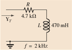
Fig. 16.69
Expert Solution & Answer
Want to see the full answer?
Check out a sample textbook solution
Students have asked these similar questions
Solve Ix and branch currents using Nodal Analysis
2. Find the current i,, iz and iz in the circuit below:
Hiz
1852
352
2.)
34
&
IN
852
31052 DIA
2A
16
852
742
√₂
1252
Det hade equations
Find hode voltages by Gauss- Jordan
Elimination
044
Chapter 16 Solutions
Introductory Circuit Analysis (13th Edition)
Ch. 16 - Find the total impedance of the parallel networks...Ch. 16 - Find the total impedance of the parallel...Ch. 16 - Prob. 3PCh. 16 - For each configuration of Fig. 16.66: a. Find the...Ch. 16 - For each configuration of Fig. 16.67 a. Find the...Ch. 16 - For each network of Fig. 16.68: a. find the total...Ch. 16 - For the circuit of Fig. 16.69: a. Find the total...Ch. 16 - Given the voltage and current shown in Fig. 16.70,...Ch. 16 - For the network in Fig. 16.71: a. Find the total...Ch. 16 - Repeat Problem 9 for the network in Fig. 16.72,...
Ch. 16 - For the network of Fig. 16.73: a. Find the total...Ch. 16 - For the network in Fig. 16.74: a. Find the total...Ch. 16 - Repeat Problem 12 for the circuit in Fig. 16.75...Ch. 16 - Calculate the currents I1 and I2 in Fig. 16.76 in...Ch. 16 - For the parallel R-C network in Fig. 16.77: a....Ch. 16 - For the parallel R-L network in Fig. 16.78: a....Ch. 16 - Plot YTandT(ofYT=YTT) for a frequency range of...Ch. 16 - Plot YTandT(ofYT=YTT) for a frequency range of...Ch. 16 - For the parallel R-L-C network in Fig. 16.79. a....Ch. 16 - For the series circuits in Fig. 16.80, find a...Ch. 16 - For the parallel circuits in Fig. 16.81, find a...Ch. 16 - For the network in Fig. 16.82: a. Calculate E, IR,...Ch. 16 - Find the element or elements that must be in the...Ch. 16 - For the network in Fig. 16.13 (usef=1kHz): a....Ch. 16 - For the network in Fig. 16.32: a. Plot the...
Additional Engineering Textbook Solutions
Find more solutions based on key concepts
Analog Voltmeter Design Figure P2-98(a) shows a voltmeter circuit consisting of a D'Arsonval meter, two series ...
ANALYSIS+DESIGN OF LINEAR CIRCUITS(LL)
Electric power systems provide energy in a variety of commercial and industrial settings. Make a list of system...
Principles and Applications of Electrical Engineering
Explain the main function of each of the following major components of a PLC: a. Processor module (CPU) b. I/O ...
Programmable Logic Controllers
Identify the type of input and output configuration for each diff-amp in Figure 18-35.
Electronics Fundamentals: Circuits, Devices & Applications
Design an ideal inverting op-amp circuit such that the voltage gain is Av=25 . The maximum current in any resis...
Microelectronics: Circuit Analysis and Design
A constant voltage of 10V is applied to a 50H inductance, as shown in Figure P3.51 Figure P3 51 The current in ...
Electrical Engineering: Principles & Applications (7th Edition)
Knowledge Booster


Learn more about
Need a deep-dive on the concept behind this application? Look no further. Learn more about this topic, electrical-engineering and related others by exploring similar questions and additional content below.Similar questions
- CIRCUITS NODAL AND MESHarrow_forward[Q3] Analyze the following electrical circuit with mesh analysis by finding the currents using Gauss-elimination method 10 Q 15 Q 25 0 20Q 35Q - 1000 V 1000V 2000 V 2000 V 30 2 40 Qarrow_forwardFor the circuit in Figure, solve the meshes and order the matrix as follows: a. What is the value of A, B, C? Response format: a complex number in rectangular format. b. What is the value of E, F, vo? Answer format: a complex number in polar form 492 -jYn HH 20/30⁰ (+ is 292 > ( 1 + 1/5 ) 00 10 The value of X=1 and Y=3 voj4arrow_forward
- Solve Io by nodal analysis not mesh analysis.. Only Nodalarrow_forward1) Referring to the circuit as in Figure 1, transform the circuit in phasor domain representation.2) Determine the value of total impedance, ZT3) Determine the value of total current, IT4) Determine the value of branch current, I1 and I25) Determine the value of voltage across resistor, R1, R2 and R36) Determine the value of voltage across capacitor, C1 and C27) Determine the value of voltage across inductor, L.arrow_forwardIn a R-C parallel circuit, total current is out of phase with the applied voltage." True False In a R-C parallel circuit, total current is out of phase with the applied voltage." True False In parallel-connected ac circuit, the value of the equivalent admittance of the circuit is equal to the phasor sum of the reciprocal of the individual admittances. " True Falsearrow_forward
- For the circuit in Figure, solve the nodes and order the matrix as follows: A B 老司圆-圆 What is the value of A, B, C? Response format: a complex number in rectangular format. d. What is the value of E, F, ix? Answer format: a complex number in polar form j2N Xi, 892 VI V₂ -j49: 30Y Z40°V The value of X=1 and Y=3 m +1 1092arrow_forwardB) Using the definition of derivative, find dx x-x if y = %3D 1-xarrow_forward3&page%3D1 American Uni. Girne American Uni.. O portal.gaueng.org My Profile - Zoom Dashboard My Courses This course Find the Norton equivalent of the circuit 60 30 40V ,50 202 A BI E E E E ere to searcharrow_forward
- hown below, By using Nodal Analysis, find R,arrow_forwardUsing Figure 1, Vs 50V-15 339 Hz R1 $1100 R2 100 www XL1 320 HH XC1 Figure 1 700 R3 600 13 R4 400 XL2 1902 XL3 450 XC2 650 a. Determine the total circuit impedance, ZT. b. Calculate current IT. c. Calculate currents I, and I3. State the value of these currents in both rectangular and polar form. d. For each of the currents determined in part c, answer the following: Is the current leading, lagging, or in phase with the source voltage. e. Use the voltage-divider rule to determine the voltages across XL1 and Xc2.arrow_forward9) Solve the nodes and order the matrix of the following way: [AB] V₁ What is the value of A and B? Response format: a complex number in rectangular format j2N Xix 8Ω V2 01 www -j49: 30Y Z40°V(+ X=1 Y=3 109arrow_forward
arrow_back_ios
SEE MORE QUESTIONS
arrow_forward_ios
Recommended textbooks for you
 Power System Analysis and Design (MindTap Course ...Electrical EngineeringISBN:9781305632134Author:J. Duncan Glover, Thomas Overbye, Mulukutla S. SarmaPublisher:Cengage Learning
Power System Analysis and Design (MindTap Course ...
Electrical Engineering
ISBN:9781305632134
Author:J. Duncan Glover, Thomas Overbye, Mulukutla S. Sarma
Publisher:Cengage Learning
Maxwell's Equations Visualized (Divergence & Curl); Author: The Science Asylum;https://www.youtube.com/watch?v=UzW_jAJzlgI;License: Standard Youtube License