
Principles of Geotechnical Engineering (MindTap Course List)
9th Edition
ISBN: 9781305970939
Author: Braja M. Das, Khaled Sobhan
Publisher: Cengage Learning
expand_more
expand_more
format_list_bulleted
Concept explainers
Videos
Textbook Question
Chapter 16, Problem 16.18P
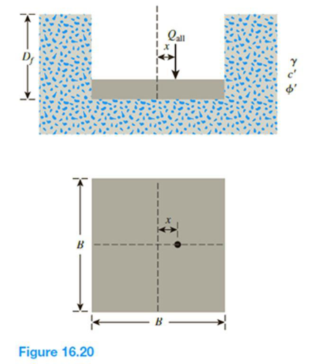
Refer to the footing in Problem 16.16. Determine the gross ultimate load the footing can carry using the Patra et al. (2015) reduction factor method for rectangular foundations given in Eqs. (16.47), (16.49), and (16.50).
16.16 A square footing on sand is subjected to an eccentric load as shown in Figure 16.20. Using Meyerhof’s effective area concept, determine the gross allowable load that the footing could carry with Fs = 4. Given: γ = 16 kN/m3, c′ = 0, ϕ′ = 29°, Df = 1.3 m, B = 1.75 m, and x = 0.25 m. Use Eqs. (16.32) through (16.42) for shape, depth, and inclination factors.
Expert Solution & Answer
Want to see the full answer?
Check out a sample textbook solution
Students have asked these similar questions
2. A building with a circular footing is constructed as the following figure. The design
building load to the footing is 9650 kN. Find the distributed stress (Aoz) and final
effective stress (o'vf) due to the circular footing at the following locations:
at the intersection point of the footing center and a depth of 5.5 m.
b. at the intersection point of the footing center and the mid-point of the clay
layer? You are tasked to find out the depth of the mid-point of the clay layer.
а.
5m
Sand
4m
Ysand = 18.5 kN/m³
%3D
Clay
Yclay = 15.8 kN/m3
%3D
| 10m
Sand
Bedrock
Center of footing
Question #3
A total load of 900 kN is uniformly distributed over a rectangular footing of size 3 x 2 m shown
in in Fig. 2. Due to the load on this footing, using influence factors determine the vertical stress
at a depth of 2.5 m
a) Under the corner at point C
b) Under the center D.
c) If another footing of size 3 x 1 m with a total load of 450 kN is constructed adjoining
the previous footing, what is the additional stress at point C at the same depth due to
the construction of the second footing?
d) Using Newmark's chart, determine the vertical stress due two both footings at a depth
of 2.5 m under point E.
C
2 m
3 m
E
3 m
1 m
2- Determine the stress increase below the center of the footing using both theoretical and approximate
methods at the top, middle and bottom of the clay layer. In addition, determine the average stress
increase for the clay layer.
Dimensions in
Heights in m
Unit weights in kN/m3
kN
m
P2
H1 H2
H3
BL
Hw
2.5
Yoati
18.0 19.0
3.0
3.0
2.0
16.0
2
3
1174
Load - 0
Hw
H1
H2
H3
OSand Clay (hoemally conactiduted)
Chapter 16 Solutions
Principles of Geotechnical Engineering (MindTap Course List)
Ch. 16 - A continuous footing is shown in Figure 16.17....Ch. 16 - Refer to Problem 16.1. If a square footing with...Ch. 16 - Redo Problem 16.1 with the following: = 115...Ch. 16 - Redo Problem 16.1 with the following: = 16.5...Ch. 16 - Redo Problem 16.1 using the modified general...Ch. 16 - Redo Problem 16.2 using the modified general...Ch. 16 - Redo Problem 16.3 using the modified general...Ch. 16 - Redo Problem 16.4 using the modified general...Ch. 16 - Prob. 16.9PCh. 16 - If the water table in Problem 16.9 drops down to...
Ch. 16 - Prob. 16.11PCh. 16 - A square footing is subjected to an inclined load...Ch. 16 - A square footing (B B) must carry a gross...Ch. 16 - Redo Problem 16.13 with the following data: gross...Ch. 16 - Refer to Problem 16.13. Design the size of the...Ch. 16 - Prob. 16.16PCh. 16 - Prob. 16.17PCh. 16 - Refer to the footing in Problem 16.16. Determine...Ch. 16 - Figure 16.21 shows a continuous foundation with a...Ch. 16 - The following table shows the boring log at a site...
Knowledge Booster


Learn more about
Need a deep-dive on the concept behind this application? Look no further. Learn more about this topic, civil-engineering and related others by exploring similar questions and additional content below.Similar questions
- Figure 16.21 shows a continuous foundation with a width of 1.8 m constructed at a depth of 1.2 m in a granular soil. The footing is subjected to an eccentrically inclined loading with e = 0.3 m, and = 10. Determine the gross ultimate load, Qu(ei), that the footing can support using: a. Meyerhof (1963) method [Eq. (16.52)] b. Saran and Agarwal (1991) method [Eq. (16.53)] c. Patra et al. (2012) reduction factor method [Eq. (16.54)]arrow_forwardRefer to the rectangular combined footing in Figure 10.1, with Q1 = 100 kip and Q2 = 150 kip. The distance between the two column loads L3 = 13.5 ft. The proximity of the property line at the left edge requires that L2 = 3.0 ft. The net allowable soil pressure is 2500 lb/ft2. Determine the breadth and length of a rectangular combined footing.arrow_forwardRepeat Problem 20.2 based on limit state design, using the factors given in Table 20.4. 20.2 A continuous foundation is required in a soil where c = 10 kN/m2, =26 and = 19.0 kN/m3. The depth of the foundation will be 1.0 m. The dead load and the live load are 600 kN/m and 400 kN/m, respectively. Determine the required width for the foundation based on allowable stress design with FS = 3, using Eq. (16.3) and Table 16.1.arrow_forward
- Q2/ Figure below shows the plane of a square footing constructed on a medium dense sand and subjected to two-ways eccentric loads , the depth of the footing is located at 3 m below the ground surface. given e,- 0.6 m, e, 0.75 m, soil properties are c-0, Neor 20, y- 18.5 kN/m, determine the ultimate load Qult- y-axis ey- 0.75 6m > x-axis e- 0.6arrow_forward(b) A plate load test was carried out on a ground having a uniform sand stratum up to sufficient depth. The size of the plate was 40 cm x 40 cm Load (kN) 5 10 20 28 38 50 56 Settlement 0.8 1.3 2.25 3.6 6 8.25 11.5 (mm) Plot the load settlement curve. Also determine the bearing capacíty and load that can be taken by a column footing of size 2m x 2m in this soil for an allowable settlement of 25 mmarrow_forwardA plate load test was carried out on a ground having a uniform sand stratum upto sufficient depth. The size of the plate used was 40 cm x 40 cm. Load (kN) 10 20 30 40 50 Settlement (mm) 2 3.5 5.5 7.5 10.5 Calculate load that can be taken by a column footing of size 3.5 m x 3.5 m in this soil, for an allowable settlement of 1.95 cmarrow_forward
- The column in the proposed rectangular footing depicted below has a size of 0.5x0.5 m. If the stress distribution is uniform, calculate the length of the footing under the design loads. M1-400 KN.m P1=1200 KN 6.50 M2 200 KN.m P1-600 KN 4arrow_forwardQ- A 2 mx 4 m rectangular footing has to carry a uniformly distributed load of 120 kPa. As per the 2:1 dispersion method of stress distribution, the increment in vertical stress (in kPa) at a depth of 2 m below the footing isarrow_forwardEx.1 A 3m×3m square footing is shown in the figure below, if the net load on the foundation is 2000 kN. A. Use strain influence factor method to calculate elastic settlement of the footing after 6 years of construction. Given to you values of tip resistance from cone penetration test: 2000 kN Depth (m) from the ground surface 9c(kN/m²) 0-2 8000 Y =17 kN/m3 2-4 10000 2m 4-6 9000 3m 6-8 8500arrow_forward
- A 2m x 4m rectangular footing has to carry a uniformly distributed load of 120 kPa. As per the 2:1 dispersion method of stress distribution, What is the increment in vertical stress (kPa) at a depth of 2 m below the footing?arrow_forwardA strip footing for a masonry wall is 1.1 m wide and is supported by the soil profile shown in the figure. What design loading can be imposed on the strip footing per meter of length? Use a factor of safety of 3. Ignore the depth factor terms in the bearing capacity calculations. However, you do want to compute the net bearing capacity, so you need to account for the weight of material removed in constructing the footing. To do this assume that the removed weight is equal to the depth of the footing multiplied by the unit weight of the upper soil. Allowable wall loading = ? 12 = 19 kN/m3 %3D D; = 1.5 m I wta Y1 = Ysub = 19 kN/m3 B = 1.1 m Soil properties: Cd = 15 kN/m² = 15 kPa Od = 28° I, = 220 %3Darrow_forwardProblem 13: A 1.5 m. x 1.5 m. square footing shown carries a concentric column load of 223 kN. Unit weight of soil is 18.9 kN/m³ and that of concrete is 23.6 kN/m³. The cohesive soil has an unconfined compressive strength of 144 kPa. 1. Compute the cohesion of soil. 2. Compute the soil contact pressure. 3. Compute the factor of safety against bearing capacity failure. Use: Terzaghi's formula: quit = 1.3c Nc + q Ng + 0.4y B Ny where: Nc = 5.14 Ng = 1.0 Ny = 0 Df = 1.2 m.arrow_forward
arrow_back_ios
SEE MORE QUESTIONS
arrow_forward_ios
Recommended textbooks for you
 Principles of Geotechnical Engineering (MindTap C...Civil EngineeringISBN:9781305970939Author:Braja M. Das, Khaled SobhanPublisher:Cengage Learning
 Fundamentals of Geotechnical Engineering (MindTap...Civil EngineeringISBN:9781305635180Author:Braja M. Das, Nagaratnam SivakuganPublisher:Cengage Learning
 Principles of Foundation Engineering (MindTap Cou...Civil EngineeringISBN:9781337705028Author:Braja M. Das, Nagaratnam SivakuganPublisher:Cengage Learning
Principles of Geotechnical Engineering (MindTap C...
Civil Engineering
ISBN:9781305970939
Author:Braja M. Das, Khaled Sobhan
Publisher:Cengage Learning
Fundamentals of Geotechnical Engineering (MindTap...
Civil Engineering
ISBN:9781305635180
Author:Braja M. Das, Nagaratnam Sivakugan
Publisher:Cengage Learning
Principles of Foundation Engineering (MindTap Cou...
Civil Engineering
ISBN:9781337705028
Author:Braja M. Das, Nagaratnam Sivakugan
Publisher:Cengage Learning
Types of Foundation in building construction in detail - Civil Engineering Videos; Author: Civil Engineers;https://www.youtube.com/watch?v=7sl4KuM4UIE;License: Standard YouTube License, CC-BY
Types of Foundation || Foundation Engineering; Author: Civil Engineering;https://www.youtube.com/watch?v=AFLuAKGhanw;License: Standard Youtube License