
Concept explainers
Videos
Solve the engine system from Sample Prob. 15.15 using the methods of Sec. 15.4B. (Hint: Define the angle between the horizontal and the crank AB as θ and derive the motion in terms of this parameter.)
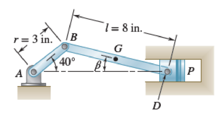
Fig. P15.146
Sample Problem 15.15
Crank AB of the engine system of Sample Prob. 15.7 has a constant clockwise angular velocity of 2000 rpm. For the crank position shown, determine the angular acceleration of the connecting rod BD and the acceleration of point D. 
Want to see the full answer?
Check out a sample textbook solution
Chapter 15 Solutions
VECTOR MECH...,STAT.+DYNA.(LL)-W/ACCESS
Additional Engineering Textbook Solutions
HEAT+MASS TRANSFER:FUND.+APPL.
Vector Mechanics for Engineers: Dynamics
Automotive Technology: Principles, Diagnosis, And Service (6th Edition) (halderman Automotive Series)
INTERNATIONAL EDITION---Engineering Mechanics: Statics, 14th edition (SI unit)
Automotive Technology: Principles, Diagnosis, and Service (5th Edition)
Machine Tool Practices (10th Edition)


- Problem 20.45 At a given instant, rod BD is rotating about the axis with an angular velocity WBD = 2 rad/s and an angular acceleration CBD = 5 rad/s2. Also, when 0 = 45° link AC is rotating at 0 = 5.0 rad/s and 6 = 2 rad/s² as shown in (Figure 1). Assume AC = 8.0 ft. Figure B WBD = 2 rad/s αBD = 5 rad/s² X A D y 0 = 45° 0 Ö= 2 rad/s² 1 of 1 Part A Determine the x, y, and z components of the velocity of point A on the link at this instant. Express your answers in feet per second using three significant figures separated by commas. (VA)z. (VA)y. (VA)z = 11.3,28.3.28.3 ft/s Submit ✓ Correct Part B Previous Answers Determine the x, y, and z components of the acceleration of point A on the link at this instant. Express your answers in feet per square second using three significant figures separated by commas. (α₁)₁₁ (α₁)y (α₁)z = Submit Provide Feedback 195| ΑΣΦ Request Answer vec ↓↑ 4 www F ? ft/s²arrow_forward4. At the instant shown, the crank AB is rotating with a constant counterclockwise angular velocity of w rpm. Determine the velocity and acceleration of point B in terms of normal and tangential components. C 4274.3420 W = rpm 45 l = 71.239 .mm ....... e mm Figure 4.arrow_forwardIn a slider crank mechanism the length of the crank OB is 181mm and length of the connecting rod is 556 mm. The center of gravity G of the connecting rod is 331 mm from the slider A. crank speed is 581 rpm clockwise. When the crank has turned 45 deg. From the inner dead center. Determine( using both relative velocity method and Instantaneous center method) 1. Velocity of the slider 2. Velocity of point G 3. Angular velocity of the connecting rod ABarrow_forward
- Q1: The crank OA of the offset sli der-crank mech anism rotates with a constant clockwise angul ar velocity o, = 12 rad/s. For the position shown: 1.1 The angular acceleration of link AB and the acceleration of B. 1.2 Locate the instantane ous center of zero velocity (IC) for the link AB. 60° 45° B OA = 75 mm %3D 15° AB = 225 mmarrow_forwardLink 2 of the mechanism shown rotates about the z-axis w.r.t. the ground (Link 1) at a constant +2rad/s. Link 3 rotates about a pin joint currently aligned with the y-axis at a constant -3rad/s. What is the angular velocity of the link? Angular velocity (rad/s): type your answer.... i+ type your answer... j+ type your answer... k. Answer with integers. Include a minus sign if necessary. Don't include a plus sign. Z A 2 3 — X ►arrow_forwardThe crank of a slider crank mechanism rotates clockwise at a constant speed of 300 r.p.m. The crank is 150 mm and the connecting rod is 600 mm long. Using vector diagrams, Determine: a). Linear velocity and acceleration of the midpoint of the connecting rod. b). Angular velocity and angular acceleration of the connecting rod, at a crank angle of 45 from inner dead centre position. c). Using trigonometry, confirm your results for the velocity and acceleration in parts (a) and (b).arrow_forward
- Problem 16.110 Figure 0.6 m 0.3 m B -0.6 m acD @CD 1 of 1 Part A αAB = Submit Determine the angular acceleration of link AB if link CD has the angular velocity WCD = 1 rad/s and angular deceleration acD = 3.2 rad/s² shown in (Figure 1). Assume the counterclockwise rotation as positive. Express your answer to three significant figures and include the appropriate units. Provide Feedback μA Value Request Answer Units 6 of 8 ? Review > Next >arrow_forwardProblem 16.143 Peg B on the gear slides freely along the slot in link AB. (Figure 1) Figure 1 of 1 150 mm %o = 3 m/s ao = 1.5 m/s² 150 mm AAAAK 600 mm Part A If the gear's center O moves with the velocity and acceleration shown, determine the angular velocity of the link at this instant. Assume the counterclockwise rotation as positive. Express your answer with the appropriate units. WAB = Submit Part B αAB = 0 Submit Value HÅ ☐☐ 2.5 Determine the angular acceleration of the link at this instant. Assume the counterclockwise rotation as positive. Express your answer with the appropriate units. Units My Answers Give Up µÅ rad 2 S B My Answers Give Up ? ?arrow_forwardProblem 16.110 The slider block has the motion shown. Suppose that r = 130 mm and h = 550 mm. (Figure 1) Figure H Type here to search B VB = 4 m/s aB = 2 m/s² 1 of 1 W = Submit Part B Determine the angular velocity of the wheel at this instant measured counterclockwise. Express your answer using three significant figures. Enter positive value if the angular velocity is counterclockwise and negative value if the angular velocity is clockwise. a = Submit ΑΣΦ Provide Feedback ↓↑ vec Request Answer ΑΣΦ Determine the angular acceleration of the wheel at this instant measured counterclockwise. Express your answer using three significant figures. Enter positive value if the angular acceleration is counterclockwise and negative value if the angular acceleration is clockwise. Request Answer W ? vec rad/s ? Next > 10:38 PM 4/14/2023arrow_forward
- Q9. Fig.9 shows a four bar linkage. The drive crank OA rotates anticlockwise at 500rpm. For the position shown determine: (a) The angular velocity of link QB (b) A The angular acceleration of link QB 16.3° 45 O Fig. 9 B 60.8 Q AB = 0.4m AO = 0.15m BQ = 0.25m OQ = 0.4m (a) (b) 28.3 rad/s (ACW) 578 rad/s² (CW)arrow_forwardLink 2 of the mechanism shown rotates about the z-axis w.r.t. the ground (Link 1) at a constant +2rad/s. Link 3 rotates about a pin joint currently aligned with the y-axis at a constant -3rad/s. What is the angular acceleration of the link? Angular acceleration (rad/s^2): type your answer.... i+ type your answer... j+ type your answer.... k. Answer with integers (include zeros). Include a minus sign if necessary. Don't include a plus sign. Z 2 3arrow_forwardThe mechanism shown is composed of rod GPV pin-connected to rod DPE at point P. Knowing that the velocity of V is 4 m/s downwards, A. Redraw bar GPV and determine its instantaneous center of rotation (label it as point C). Specify all angles and distances needed. B. Determine the angular velocity of rod GPV. C. Determine the velocity of point P. D. Redraw bar DPE and determine its instantaneous center of rotation (label it as point C). Specify all angles and distances needed. E. Determine the angular velocity of rod DPE. Use IC method. Please don't show me the answer in chegg. I think there is an errorarrow_forward
 Elements Of ElectromagneticsMechanical EngineeringISBN:9780190698614Author:Sadiku, Matthew N. O.Publisher:Oxford University Press
 Mechanics of Materials (10th Edition)Mechanical EngineeringISBN:9780134319650Author:Russell C. HibbelerPublisher:PEARSON
 Thermodynamics: An Engineering ApproachMechanical EngineeringISBN:9781259822674Author:Yunus A. Cengel Dr., Michael A. BolesPublisher:McGraw-Hill Education
 Control Systems EngineeringMechanical EngineeringISBN:9781118170519Author:Norman S. NisePublisher:WILEY
 Mechanics of Materials (MindTap Course List)Mechanical EngineeringISBN:9781337093347Author:Barry J. Goodno, James M. GerePublisher:Cengage Learning
 Engineering Mechanics: StaticsMechanical EngineeringISBN:9781118807330Author:James L. Meriam, L. G. Kraige, J. N. BoltonPublisher:WILEY