
Statics and Mechanics of Materials (5th Edition)
5th Edition
ISBN: 9780134382593
Author: Russell C. Hibbeler
Publisher: PEARSON
expand_more
expand_more
format_list_bulleted
Videos
Textbook Question
Chapter 15.2, Problem 9P
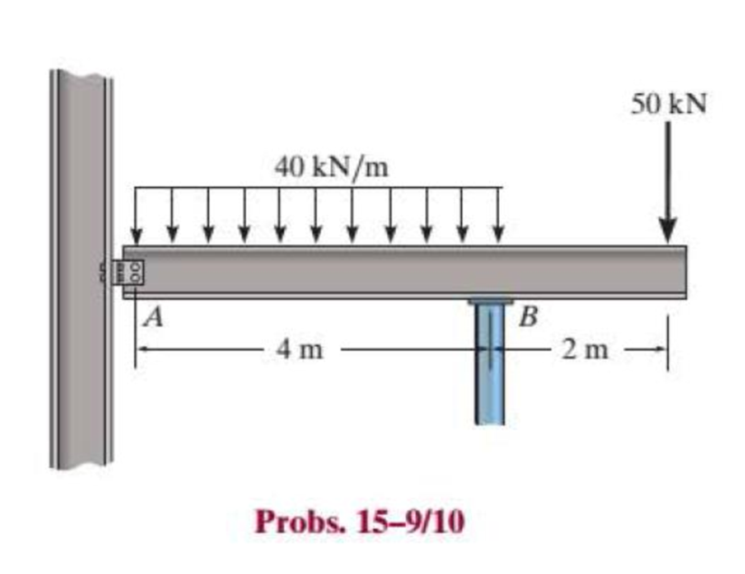
Select the lightest W360 wide-flange beam from Appendix B that can safely support the loading. The beam has an allowable normal stress of σallow = 150 MPa and an allowable shear stress of τallow = 80 MPa. Assume there is a pin at A and a roller support at B.
Expert Solution & Answer
Want to see the full answer?
Check out a sample textbook solution
Students have asked these similar questions
The simply supported joist is used in the construction of a floor for a building. In order to keep the floor low with respect to the sill beams C and D, the ends of the joist are notched as shown. If the allowable shear stress is tallow = 350 psi and the allowable bending stress is s allow = 1700 psi, determine the smallest height h so that the beam will support a load of P = 600 lb. Also, will the entire joist safely support the load? Neglect the stress concentration at the notch.
Determine the maximum uniform distributed load w0 that can be supported by the reinforced concrete beam if the allowable tensile stress for the steel is (sst)allow = 28 ksi and the allowable compressive stress for the concrete is (sconc)allow = 3 ksi. Assume the concrete cannot support a tensile stress. Take Est = 29(103) ksi, Econc = 3.6(103) ksi.
The box beam is made by nailing four 2-in. by 8-in. plankstogether as shown. Given that w0 = 300 lb/ft, find the largestallowable force P if the bending stress is limited to 1400 psi.
Chapter 15 Solutions
Statics and Mechanics of Materials (5th Edition)
Ch. 15.2 - Determine the minimum dimension a to the nearest...Ch. 15.2 - Prob. 2FPCh. 15.2 - Prob. 3FPCh. 15.2 - Determine the minimum dimension h to the nearest...Ch. 15.2 - Prob. 5FPCh. 15.2 - Select the lightest W410-shaped section that can...Ch. 15.2 - The beam is made of timber that has an allowable...Ch. 15.2 - Determine the minimum width of the beam to the...Ch. 15.2 - Determine the minimum width of the beam to the...Ch. 15.2 - The brick wall exerts a uniform distributed load...
Ch. 15.2 - Select the lightest-weight wide-flange beam from...Ch. 15.2 - Prob. 6PCh. 15.2 - Select the lightest-weight wide-flange beam with...Ch. 15.2 - Select the lightest-weight wide-flange beam from...Ch. 15.2 - Select the lightest W360 wide-flange beam from...Ch. 15.2 - Investigate if the W250 58 beam can safely...Ch. 15.2 - The beam is constructed from two boards. If each...Ch. 15.2 - The joists of a floor in a warehouse are to be...Ch. 15.2 - The timber beam has a width of 6 in. Determine its...Ch. 15.2 - The beam is constructed from four boards. If each...Ch. 15.2 - The beam is constructed from two boards. If each...Ch. 15.2 - If the cable is subjected to a maximum force of P...Ch. 15.2 - If the W360 45 wide-flange beam has an allowable...Ch. 15.2 - If P = 800 lb, determine the minimum dimension a...Ch. 15.2 - If a = 3 in. and the wood has an allowable normal...Ch. 15.2 - The beam is constructed from three plastic strips....Ch. 15.2 - If the allowable bending stress is allow = 6 MPa,...Ch. 15.2 - The beam is made of Douglas fir having an...Ch. 15.2 - Select the lightest-weight wide-flange beam from...Ch. 15.2 - Draw the shear and moment diagrams for the shaft,...Ch. 15.2 - Draw the shear and moment diagrams for the shaft,...
Knowledge Booster


Learn more about
Need a deep-dive on the concept behind this application? Look no further. Learn more about this topic, mechanical-engineering and related others by exploring similar questions and additional content below.Similar questions
- A box is produced by joining the wooden and plywood rectangular elements with screws as shown in the section. The shear force that each screw used in the cross section joint can safely carry is V = 2 kN. If the beam element created in this way is loaded from the middle of the span with a load of P = 100 kN, find the screw gap a and the total number of screws to be used in the beam element. (Cross-section dimensions t = 15mm, b = 150mm, c = 30mm, h = 180mm; beam support span L = 5m)arrow_forwardA beam made of timber is required to span 5m and has dimensions of 75mm x 250mm. If the beam is simply supported and carries a point load of 40KN. Determine the safe allowable stress due to bending. Let: M max= WL/4 Mr= fz Z=bd2/6arrow_forwardThe overhanging beam ABC of span 5.4 m is constructed of a W360 X 216 rolled-aluminium shape. It carries uniformly distributed load, ω of 35 kN/m and point loads of P1 = 30 kN and P2 = 25 kN. b) Find the maximum shear force and maximum bending moment of the beam. After that, Evaluate factor of safety for the beam shown, if the ultimate normal stress for aluminium is 110 MPa.arrow_forward
- AW410 x 60 standard steel shape is used to support the loads shown on the beam in the figure. Assume P = 125 kN, w = 25 kN/m, a = 3.1 m, and b = 2.0m. Determine the magnitude and location of the maximum bending stress in the beam. A omax a B a Pin b MPa E W D a Earrow_forwardProblem 1: Slab design using the ACI moment coefficients Design the continuous slab shown using the ACI moment coefficients assuming the concrete weighs 24 kN/m3 and that a service live load of 15 kN/m is to be supported. The slabs are built integrally with the end supports, which are spandrel beams. fy= 420 MPa and f'c = 28 MPa. Draw a plan and section showing all reinforcements along the slab. E 7m - 6 m + 7m --arrow_forwardCalculate the shear stresses at point A in the adjacent T-beam.F(maks)= 200 kNarrow_forward
- Problem 3 only, solve carefully, include the units in every step and draw the diagram. Thanks! In a 2.5 m cantilevered I-beam, 2500 kg weight is applied at 0.75 meter from the free end. If the allowable stress inbeam is 120 Mpa, determine theA. section modulus, in3 B. The base and height of the beam if the base is 75% of its height, mmarrow_forwardThe overhang beam is constructed using two 2-in. by 4-in. pieces of wood braced as shown. If the allowable bending stress is sallow = 600 psi, determine the largest load P that can be applied. Also, determine the maximum spacing of nails, s, along the beam section AC if each nail can resist a shear force of 800 lb. Assume the beam is pin connected at A, B, and D. Neglect the axial force developed in the beam along DA.arrow_forward1. For the same beam used in IC-13, determine the jump in shear stress at the web-flange junction (at point A). V = 20KN. A 200 mm 20 mm B 200 mm 20 mm 300 mm 2. Now cut off the bottom flange and recalculate the maximum shear stress. (Remove the bottom flange so that the beam has a T-shaped cross-section.)arrow_forward
- Find the maximum stress in the beam if it is fixed at the left end,free at the right end subjected to a uniform distributed load of200 lb/in.arrow_forwardThe beam is supported by a pin at point A and a roller at kN point B. A distributed load of W₁ = 8 - and an applied m force of F₁ = 12 kN are applied to the beam. The beam has an allowable bending stress of allow = 6 MPa. Neglect the weight and thickness of the beam. Take the origin for all functions to be at A., i.e. start at the left and go right. Must use positive sign convention for V and M. d3 1 d3 d1 W1 d1 B O h d2 F₁ Values for the figure are given in the following table. Note the figure may not be to scale. Dimensions for the whole beam Variable Value d₁ 4 m d₂ 2 marrow_forward. A horizontal beam with a rectangular cross section (2 inch x 6 inch) is loaded as shown with P1= 5 kipsand P2 = 10 kips. Determine the maximum normal stress in the beamarrow_forward
arrow_back_ios
SEE MORE QUESTIONS
arrow_forward_ios
Recommended textbooks for you
 Elements Of ElectromagneticsMechanical EngineeringISBN:9780190698614Author:Sadiku, Matthew N. O.Publisher:Oxford University Press
 Mechanics of Materials (10th Edition)Mechanical EngineeringISBN:9780134319650Author:Russell C. HibbelerPublisher:PEARSON
 Thermodynamics: An Engineering ApproachMechanical EngineeringISBN:9781259822674Author:Yunus A. Cengel Dr., Michael A. BolesPublisher:McGraw-Hill Education
 Control Systems EngineeringMechanical EngineeringISBN:9781118170519Author:Norman S. NisePublisher:WILEY
 Mechanics of Materials (MindTap Course List)Mechanical EngineeringISBN:9781337093347Author:Barry J. Goodno, James M. GerePublisher:Cengage Learning
 Engineering Mechanics: StaticsMechanical EngineeringISBN:9781118807330Author:James L. Meriam, L. G. Kraige, J. N. BoltonPublisher:WILEY
Elements Of Electromagnetics
Mechanical Engineering
ISBN:9780190698614
Author:Sadiku, Matthew N. O.
Publisher:Oxford University Press
Mechanics of Materials (10th Edition)
Mechanical Engineering
ISBN:9780134319650
Author:Russell C. Hibbeler
Publisher:PEARSON
Thermodynamics: An Engineering Approach
Mechanical Engineering
ISBN:9781259822674
Author:Yunus A. Cengel Dr., Michael A. Boles
Publisher:McGraw-Hill Education
Control Systems Engineering
Mechanical Engineering
ISBN:9781118170519
Author:Norman S. Nise
Publisher:WILEY
Mechanics of Materials (MindTap Course List)
Mechanical Engineering
ISBN:9781337093347
Author:Barry J. Goodno, James M. Gere
Publisher:Cengage Learning
Engineering Mechanics: Statics
Mechanical Engineering
ISBN:9781118807330
Author:James L. Meriam, L. G. Kraige, J. N. Bolton
Publisher:WILEY
Mechanics of Materials Lecture: Beam Design; Author: UWMC Engineering;https://www.youtube.com/watch?v=-wVs5pvQPm4;License: Standard Youtube License