
Statics and Mechanics of Materials (5th Edition)
5th Edition
ISBN: 9780134382593
Author: Russell C. Hibbeler
Publisher: PEARSON
expand_more
expand_more
format_list_bulleted
Videos
Textbook Question
Chapter 15.2, Problem 4P
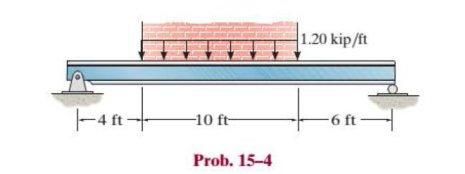
The brick wall exerts a uniform distributed load of 1.20 kip/ft on the beam. If the allowable bending stress is σallow = 22 ksi and the allowable shear stress is τallow = 12 ksi, select the lightest wide-flange section with the shortest depth from Appendix B that will safely support the load. If there are several choices of equal weight, choose the one with the shortest height.
Expert Solution & Answer
Want to see the full answer?
Check out a sample textbook solution
Students have asked these similar questions
The simply supported joist is used in the construction of a floor for a building. In order to keep the floor low with respect to the sill beams C and D, the ends of the joist are notched as shown. If the allowable shear stress is tallow = 350 psi and the allowable bending stress is s allow = 1700 psi, determine the smallest height h so that the beam will support a load of P = 600 lb. Also, will the entire joist safely support the load? Neglect the stress concentration at the notch.
Find the second moment of area, the location of the neutral axis, and the distances from the neutral axis to the top and
bottom surfaces. Consider that the section is transmitting a positive bending moment about the z axis, Mz, where M₂ = 10
kip-in if the dimensions of the section are given in ips units, or M₂ = 1.13 kN·m if the dimensions are in Sl units. Determine
the resulting stresses at the top and bottom surfaces and at every abrupt change in the cross section.
From the figure
Z
1 in
112
in
y
in → ← ¹ in
12
in
D
C
B
A
++
in
The area is determined to be 2.0625 in².
The distances from the neutral axis to the top and bottom surfaces are determined to be 0.858 x in and
The second moment of area is determined to be 0.447 in 4.
1.017
xin.
Find the second moment of area, the location of the neutral axis, and the distances from the neutral axis to the top and
bottom surfaces. Consider that the section is transmitting a positive bending moment about the z axis, Mz, where M₂ = 10
kip-in if the dimensions of the section are given in ips units, or M₂ = 1.13 kN·m if the dimensions are in Sl units. Determine
the resulting stresses at the top and bottom surfaces and at every abrupt change in the cross section.
From the figure,
с
- 12.5
B
A
y
I
50
100
75
12.5-
12.5
25
D
100
The area is determined to be 3750 mm²
The distances from the neutral axis to the top and bottom surfaces are determined to be 57.292
The second moment of area is determined to be 4.293
x 106 mm4.
mm and 42.708 ✪ mm.
Chapter 15 Solutions
Statics and Mechanics of Materials (5th Edition)
Ch. 15.2 - Determine the minimum dimension a to the nearest...Ch. 15.2 - Prob. 2FPCh. 15.2 - Prob. 3FPCh. 15.2 - Determine the minimum dimension h to the nearest...Ch. 15.2 - Prob. 5FPCh. 15.2 - Select the lightest W410-shaped section that can...Ch. 15.2 - The beam is made of timber that has an allowable...Ch. 15.2 - Determine the minimum width of the beam to the...Ch. 15.2 - Determine the minimum width of the beam to the...Ch. 15.2 - The brick wall exerts a uniform distributed load...
Ch. 15.2 - Select the lightest-weight wide-flange beam from...Ch. 15.2 - Prob. 6PCh. 15.2 - Select the lightest-weight wide-flange beam with...Ch. 15.2 - Select the lightest-weight wide-flange beam from...Ch. 15.2 - Select the lightest W360 wide-flange beam from...Ch. 15.2 - Investigate if the W250 58 beam can safely...Ch. 15.2 - The beam is constructed from two boards. If each...Ch. 15.2 - The joists of a floor in a warehouse are to be...Ch. 15.2 - The timber beam has a width of 6 in. Determine its...Ch. 15.2 - The beam is constructed from four boards. If each...Ch. 15.2 - The beam is constructed from two boards. If each...Ch. 15.2 - If the cable is subjected to a maximum force of P...Ch. 15.2 - If the W360 45 wide-flange beam has an allowable...Ch. 15.2 - If P = 800 lb, determine the minimum dimension a...Ch. 15.2 - If a = 3 in. and the wood has an allowable normal...Ch. 15.2 - The beam is constructed from three plastic strips....Ch. 15.2 - If the allowable bending stress is allow = 6 MPa,...Ch. 15.2 - The beam is made of Douglas fir having an...Ch. 15.2 - Select the lightest-weight wide-flange beam from...Ch. 15.2 - Draw the shear and moment diagrams for the shaft,...Ch. 15.2 - Draw the shear and moment diagrams for the shaft,...
Knowledge Booster


Learn more about
Need a deep-dive on the concept behind this application? Look no further. Learn more about this topic, mechanical-engineering and related others by exploring similar questions and additional content below.Similar questions
- Q1/ A composite beam is made of wood and reinforced with steel strap located on its bottom side. It has the cross-sectional area shown in fig. if the beam is subjected to a bending moment of M=2kN.m, determine the normal stress at wood and steel. Take Ew=12Gpa and Est=200Gpa. 150mm Wood en 20mm Steel 150mmarrow_forwardIf the simply supported beam is subjected to the load shown below, determine the following: c- c - The internal bending moment acting on the cross-section through point C. d- d- The shear stress at section C.arrow_forwardQuestion 3 Determine the maximum bending stress in the steel beam in psi with the circular cross section. 400 lb 200 lb/ft D 2 in. -5 ft- -4 ft-arrow_forward
- The overhang beam is constructed using two 2-in. by 4-in. pieces of wood braced as shown. If the allowable bending stress is sallow = 600 psi, determine the largest load P that can be applied. Also, determine the maximum spacing of nails, s, along the beam section AC if each nail can resist a shear force of 800 lb. Assume the beam is pin connected at A, B, and D. Neglect the axial force developed in the beam along DA.arrow_forwardA beam made of timber is required to span 5m and has dimensions of 75mm x 250mm. If the beam is simply supported and carries a point load of 40KN. Determine the safe allowable stress due to bending. Let: M max= WL/4 Mr= fz Z=bd2/6arrow_forwardThe beam is supported by a pin at point A and a roller at kN point B. A distributed load of W₁ = 8 - and an applied m force of F₁ = 12 kN are applied to the beam. The beam has an allowable bending stress of allow = 6 MPa. Neglect the weight and thickness of the beam. Take the origin for all functions to be at A., i.e. start at the left and go right. Must use positive sign convention for V and M. d3 1 d3 d1 W1 d1 B O h d2 F₁ Values for the figure are given in the following table. Note the figure may not be to scale. Dimensions for the whole beam Variable Value d₁ 4 m d₂ 2 marrow_forward
- 1. For the simply supported beam with a T-shape cross-section as shown below, a- Draw the shear and moments diagram of the beam. b- Determine the maximum normal bending stress and specify its location. C- If the beam made from two boards determines the maximum shear stress in the glue necessary to hold the boards together along the seam where they are joined. d- Determine the shear stress at point B. 4 m 6.5 kN/m 6m- Glue 150 mm 30 mm 150 mm 30 mmarrow_forwardDetermine the internal normal force and shear force, and the bending moment in the beam at points C and D. Assume the support at B is a roller. Point C is located just to the right of the 8-kip load. For your explanation section, complete a FBD of the other side of the beam from the version you did to solve the problem. 8 kip 40 kip · ft A to to D B- 8 ft 8 ft- -8 ftarrow_forwardDetermine the shear stress (in Mpa) in the 28.54-mm-diameter pin at B that support the beam if P = 35.79 kN, a = 2.76 m, and b = 5.95 m.arrow_forward
- The axle of the freight train is subjected to loadings as shown below. The diameter of the axle is 137.5 mm. If it is supported by two journal bearings at C and D, determine the maximum bending Stress. Include a FBD, SFD and BMD using either the section or graphical method. Draw a cross-section of the shaft and indicate the points of maximum tension and compression.arrow_forwardIn a 2.5 cantilevered I-beam, 2500 kg weight is applied at 0.75 meter from the free end. If the allowable stress in beam is 120 Mpa, determine the section modulus and The base and height of the beam if the base is 75% of its height mm.arrow_forwardQUESTION 3 If the allowable bending stresses for a beam in one application is 6 kip/in2 in tension. The cross-section of the beam is W8 x 40. If the beam is 10 foot long and simply supported and has a concentrated load applied at x = 3 ft as shown below. • Generate the shear force and bending moment diagram in terms of P; • Based on the allowable maximum bending moment you just obtained above, calculate/ input the mazimm allowable value of the load P: please, pay attention to units, and calculate your answer to 1 decimal place.. 3 ft 7 ft kip.arrow_forward
arrow_back_ios
SEE MORE QUESTIONS
arrow_forward_ios
Recommended textbooks for you
 Elements Of ElectromagneticsMechanical EngineeringISBN:9780190698614Author:Sadiku, Matthew N. O.Publisher:Oxford University Press
 Mechanics of Materials (10th Edition)Mechanical EngineeringISBN:9780134319650Author:Russell C. HibbelerPublisher:PEARSON
 Thermodynamics: An Engineering ApproachMechanical EngineeringISBN:9781259822674Author:Yunus A. Cengel Dr., Michael A. BolesPublisher:McGraw-Hill Education
 Control Systems EngineeringMechanical EngineeringISBN:9781118170519Author:Norman S. NisePublisher:WILEY
 Mechanics of Materials (MindTap Course List)Mechanical EngineeringISBN:9781337093347Author:Barry J. Goodno, James M. GerePublisher:Cengage Learning
 Engineering Mechanics: StaticsMechanical EngineeringISBN:9781118807330Author:James L. Meriam, L. G. Kraige, J. N. BoltonPublisher:WILEY
Elements Of Electromagnetics
Mechanical Engineering
ISBN:9780190698614
Author:Sadiku, Matthew N. O.
Publisher:Oxford University Press
Mechanics of Materials (10th Edition)
Mechanical Engineering
ISBN:9780134319650
Author:Russell C. Hibbeler
Publisher:PEARSON
Thermodynamics: An Engineering Approach
Mechanical Engineering
ISBN:9781259822674
Author:Yunus A. Cengel Dr., Michael A. Boles
Publisher:McGraw-Hill Education
Control Systems Engineering
Mechanical Engineering
ISBN:9781118170519
Author:Norman S. Nise
Publisher:WILEY
Mechanics of Materials (MindTap Course List)
Mechanical Engineering
ISBN:9781337093347
Author:Barry J. Goodno, James M. Gere
Publisher:Cengage Learning
Engineering Mechanics: Statics
Mechanical Engineering
ISBN:9781118807330
Author:James L. Meriam, L. G. Kraige, J. N. Bolton
Publisher:WILEY
Everything About TRANSVERSE SHEAR in 10 Minutes!! - Mechanics of Materials; Author: Less Boring Lectures;https://www.youtube.com/watch?v=4x0E9yvzfCM;License: Standard Youtube License