
Videos
For the circuit in Fig. 15.55, (a) derive an algebraic expression for the transfer function H(jω) = iout/vin in terms of circuit components R1, R2, L1, and L2; (b) evaluate the the magnitude of H(jω) at frequencies of 10 kHz, 1 MHz, and 100 MHz for the case where R1 = 3 kΩ, R2 = 12 kΩ, L1 = 5 mH, and L2 = 8 mH; (c) qualitatively, explain the behavior of the transfer function magnitude frequency response.
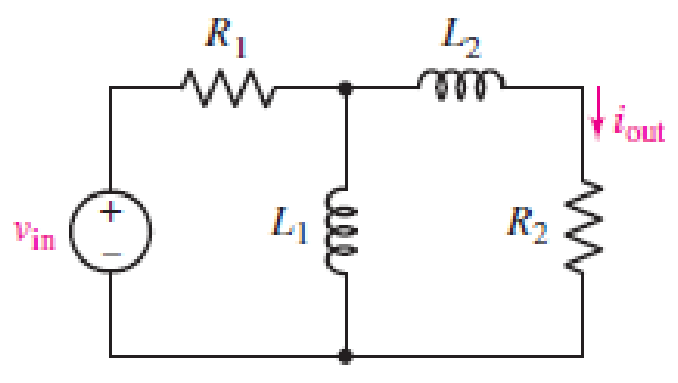
■ FIGURE 15.55
(a)
Find an algebraic expression for the transfer function
Answer to Problem 5E
The transfer function
Explanation of Solution
Given data:
Refer to Figure 15.55 in the textbook.
Formula used:
Write the expression to calculate the impedance of the passive elements resistor and inductor.
Here,
Calculation:
The given circuit is redrawn as Figure 1.
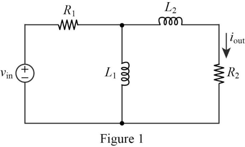
The impedance circuit of the Figure 1 is drawn as Figure 2 using the equations (1) and (2).
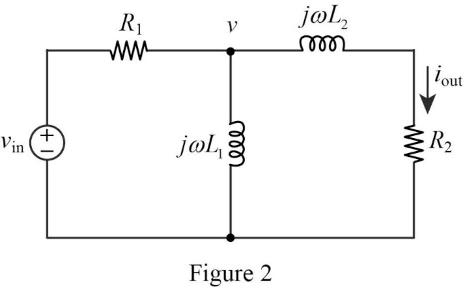
Write the general expression to calculate the transfer function of the circuit in Figure 2.
Here,
Use nodal analysis on node
Rearrange the above equation to find
The output current
Substitute
Simplify the above equation to find
Substitute
Conclusion:
Thus, the transfer function
(b)
Find the value of magnitude of
Answer to Problem 5E
The value of magnitude of the transfer function
Explanation of Solution
Given data:
The value of the resistor 1
The value of the resistor 2
The value of the inductor 1
The value of the inductor 2
Formula used:
Write the expression to calculate the angular frequency.
Here,
Calculation:
From part (a), the transfer function is,
Substitute
Substitute
For frequency of 10 kHz:
Substitute
Take magnitude for above equation to find
For frequency of 1 MHz:
Substitute
Take magnitude for above equation to find
For frequency of 100 MHz:
Substitute
Take magnitude for above equation to find
Conclusion:
Thus, the value of magnitude of the transfer function
(c)
Explain the behavior of the transfer function magnitude frequency response.
Explanation of Solution
Discussion:
At lower frequencies
It is clear that the current
The magnitude approaches zero at low and high frequencies and at medium frequencies, the magnitude approaches maximum value. It implies the characteristics of the band-pass filter.
Conclusion:
Thus, the behavior of the transfer function magnitude frequency response is explained.
Want to see more full solutions like this?
Chapter 15 Solutions
Loose Leaf for Engineering Circuit Analysis Format: Loose-leaf
Additional Engineering Textbook Solutions
Fundamentals of Electric Circuits
Basic Engineering Circuit Analysis
ANALYSIS+DESIGN OF LINEAR CIRCUITS(LL)
Electric Motors and Control Systems
Electric Circuits. (11th Edition)
Introductory Circuit Analysis (13th Edition)


- A series RLC circuit is formed using component values R=100 and L=1.5 mH, together with a source that provides a sinusoidal voltage Vs (t). If the quality factor in resonance condition is Q0 = 7, determine: a) the magnitude of the impedance at 500 Mrad s-1b) the current that circulates if vs (t) = 2,5V cos (425 ×10 6t) Note: Vent (input voltage). Vsal (output voltage)arrow_forwardA series L–R–C circuit has a supply input of 5 volts. Given that inductance, L = 5 mH, resistance, R = 75ohm and capacitance, C = 0.2µF, determine (a) the resonant frequency, (b) the value of voltage across the capacitor at the resonant frequency, (c) the frequency at which the p.d. across the capacitance is a maximum and (d) the value of the maximum voltage across the capacitor. A capacitor having a Q-factor of 250 is con nected in series with a coil which has a Q-factor of 80. Calculate the overall Q-factor of the circuit.arrow_forward1. An impedance coil takes 144 watts at a lagging power factor of 0.6. What value of capacitanceand resistance should be connected in series with the coil if the power input to the latter is toremain unchanged and the overall power factor is to be unity (in resonance)? The circuit isenergized by a 120 volt, 60 cps source.2. A series RLC circuit has a Q of 75 and a pass band between half-power frequencies of 160 cps.Calculate the frequency of resonance and upper and lower frequencies of the pass band.3. An impedance coil having a resistance of 30 ohms and a 50 cps inductive reactance of 33.3 ohmsis connected to a 125 volt 60 cps source. A series circuit consisting of a 20 ohm resistor and avariable capacitor is then connected in parallel with the coil. (a) for what values of capacitancewill the circuit be in resonance? (b) calculate the two values of line current for the condition ofresonance.4. A parallel-series filter like that of Fig. 13.10b in the scanned copy of the on page 364 is…arrow_forward
- 21. Plot the magnitude frequency response for the system G(S)=1/(S(1+0.5S)(1+0.1S))). Also determine gain cross over frequency.arrow_forwardCharacteristic equation of a system is given by, s2+3s+31=0 The value of resonant frequency is: Answerarrow_forwardCalculate all the values from the formulas given below: Area = 402.88mm^2, Capacitance = 1.11592 x 10^-10 F length = 12.03 mm, fr (resonance frequency) = 108828.238, fa (anti resonance frequency) = 145987.807, Diameter of cylinder = 4mm, Mass of cylinder = 4.38g,arrow_forward
- y[z]=6cos2(pi×z/4)a.The above equation shows a discrete time signal, y[z] from a device, determine the four point DFT of the sequence.H(ejw) = {1, 0≤|w|≤wC {0, WC |W|< π b.The expression above shows the DTFT of a lowpass filter system. In order to get the impulse response h[n], determine the inverse DTFT of the systemarrow_forwardBy a suitable graphical representation sketch signal voltage (V) against period (t) of an FM System at t ranges from 1sec to 12sec. Taken magnitude of signal voltage to be 10V, 2pifc = 10*108, 2pifm = 3000, carrier deviation is 2.337KHz. please step by step solution. You are required to show workarrow_forwardA coil of inductance 200µH and resistance 50.27ohms and a variable capacitor are connected in series to a 5 mV supply of frequency 2MHz. Determine (a) the value of capacitance to tune the circuit to resonance, (b) the supply current at resonance, (c) the p.d. across the capacitor at resonance,the bandwidth, and the half-power frequencies Answers: C= 31.66 pF,I= 99.46 µA,P.D= 250 mV, bandwidth=40 kHz, and half power frequency= 2.02 MHz, 1.98 MHzarrow_forward
- An angle modulated signal with carrier frequency ωc = (2π*106 ) is described by the equation, Φ(t) = 10 cos (ωc t + 0.1 sin 2000 πt) (a) Find power in modulated signal (b) Find frequency deviation Δf (c) Find phase deviation Δφ (d) Estimate bandwidth of Φ(t)arrow_forwardFind the gain of the following circuit and the lower and upper cutoff frequencies. (RS = 1 kΩ, R1 = 40 kΩ, R2 = 10kΩ, RC = 20 kΩ, RE = 30 kΩ, RL = 2.2 kΩ, CS = 10 µF, CC = 1 µF, CE = 20 µF, Cbe = 20 pF, Cbc = 30 pF,VT = 26mV, β = 100, ro = infinityarrow_forwardA summary of the results is as follows: Frequency = 1.01 kHz: Input = 1.51 V; Output = 1.44 V Frequency = 10.06 kHz: Input = 1.37 V; Output = 0.62 V Frequency = 102.8 kHz: Input = 1.31 V; Output = 90 mV The resistor was measured to be 331.4 Ω and the capacitor to be 96.3 nF. (1) Calculate values of the transfer function, using the formula above, at the frequencies that were investigated and compare them to the ratios of the measured output and input voltages at each frequency. A summary of the results is as follows: Frequency = 1.01 kHz: Input = 1.50 V; Output = 1.44 V Frequency = 10.06 kHz: Input = 1.20 V; Output = 0.50 V Frequency = 102.8 kHz: Input = 1.13 V; Output = 70 mV The resistor was measured to be 150.1 Ω and the capacitor to be 233.6 nF. (2) Are the ratios of the output voltage to input voltage for this filter similar to the ratios of the first low-pass filter? Does it make sense based on the transfer function how the ratios compare?arrow_forward
 Introductory Circuit Analysis (13th Edition)Electrical EngineeringISBN:9780133923605Author:Robert L. BoylestadPublisher:PEARSON
 Delmar's Standard Textbook Of ElectricityElectrical EngineeringISBN:9781337900348Author:Stephen L. HermanPublisher:Cengage Learning
 Programmable Logic ControllersElectrical EngineeringISBN:9780073373843Author:Frank D. PetruzellaPublisher:McGraw-Hill Education
 Fundamentals of Electric CircuitsElectrical EngineeringISBN:9780078028229Author:Charles K Alexander, Matthew SadikuPublisher:McGraw-Hill Education
 Electric Circuits. (11th Edition)Electrical EngineeringISBN:9780134746968Author:James W. Nilsson, Susan RiedelPublisher:PEARSON
 Engineering ElectromagneticsElectrical EngineeringISBN:9780078028151Author:Hayt, William H. (william Hart), Jr, BUCK, John A.Publisher:Mcgraw-hill Education,