
Concept explainers
Videos
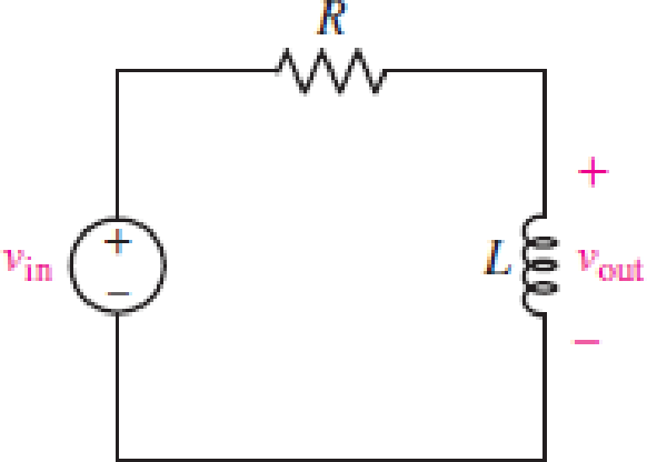
For the RL circuit in Fig. 15.52, (a) determine the transer function defined as H(jω) = vout/vin; (b) for the case of R = 200 Ω and L = 5 mH, construct a plot of the magnitude and phase as a function of frequency; and (c) evaluate the magnitude and phase at a frequency of 10 kHz.
FIGURE 15.52
(a)
Find the transfer function
Answer to Problem 1E
The transfer function
Explanation of Solution
Given data:
Refer to Figure 15.52 in the textbook.
Formula used:
Write the expression to calculate the impedance of the passive elements resistor and inductor.
Here,
Calculation:
The given RL circuit is drawn as Figure 1.
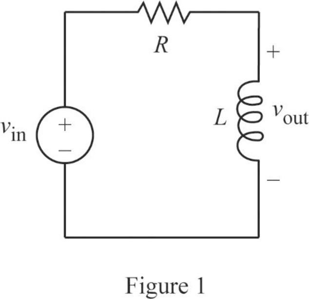
The Figure 1 is redrawn as impedance circuit in Figure 2 using the equations (1) and (2).
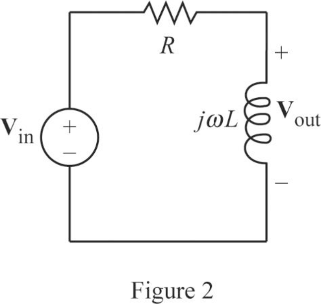
Write the general expression to calculate the transfer function of the circuit in Figure 2.
Here,
Apply Kirchhoff’s voltage law on Figure 2 to find
Rearrange the above equation to find
Substitute
Conclusion:
Thus, the transfer function
(b)
Plot the magnitude and phase as a function of frequency.
Explanation of Solution
Given data:
The value of the resistor
The value of the inductor
Calculation:
From part (a), the transfer function is,
Substitute
Simplify the above equation to find
Re-write the transfer function
From equation (4), the magnitude function of
Write the above equation in decibel (dB).
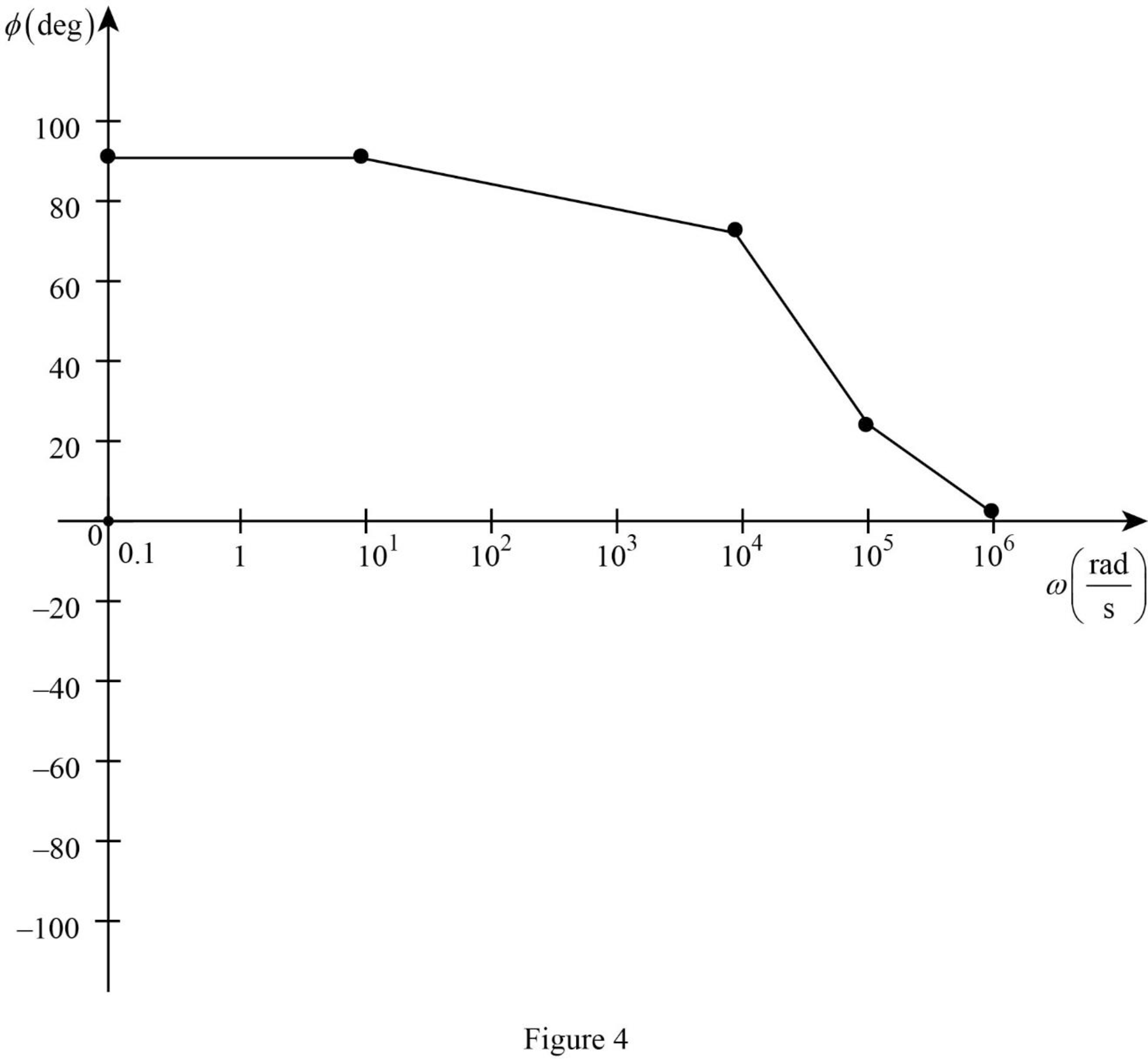
From equation (4), the phase angle is expressed as follows:
Substitute
Substitute
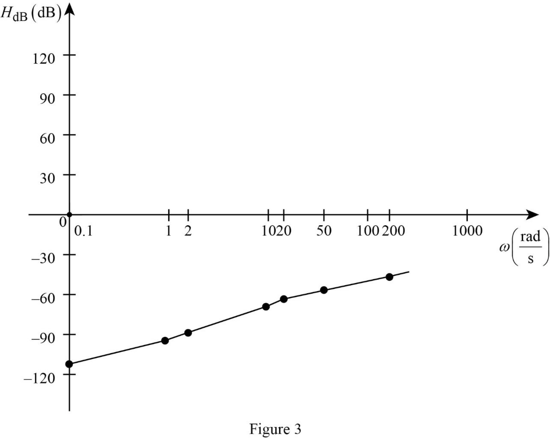
Similarly, by substituting various values for
Table 1
| 0.1 | 1 | 2 | 10 | 20 | 50 | 200 | |
| –112 | –92 | –86 | –72 | –66 | –58 | –46 |
Table 2
| 0.1 | 10 | 104 | 105 | 106 | |
| 90 | 90 | 75.96 | 21.8 | 2.3 |
The Figure 1 is the magnitude plot of the given transfer function obtained using Table 1.
The Figure 2 is the phase plot of the given transfer function obtained using Table 2.
Conclusion:
Thus, the magnitude and phase as a function of frequency is plotted.
(c)
Find the value of the magnitude and phase at a frequency of
Answer to Problem 1E
The value of the magnitude and phase at a frequency of
Explanation of Solution
Given data:
The value of the frequency
Formula used:
Write the expression to calculate the angular frequency.
Here,
Calculation:
From part (a), the transfer function is expressed as,
From equation (7), the magnitude function is expressed as,
Substitute
Substitute
From equation (7), the phase function is expressed as,
Substitute
Substitute
Conclusion:
Thus, the value of the magnitude and phase at a frequency of
Want to see more full solutions like this?
Chapter 15 Solutions
Loose Leaf for Engineering Circuit Analysis Format: Loose-leaf
Additional Engineering Textbook Solutions
ELECTRICITY FOR TRADES (LOOSELEAF)
Fundamentals of Electric Circuits
Introductory Circuit Analysis (13th Edition)
Electric Circuits (10th Edition)
Fundamentals of Applied Electromagnetics (7th Edition)
Basic Engineering Circuit Analysis


- R= 300 ohm, L= 40 mH, C= 600nF, V(AC)=5 Volt, F= 100 Hz Calculate theoretically the voltages XL (Inductance = Resistance of the coil), XC (Capacitance = resistance of the capacitor), Z (Impedance = Equivalent resistance of the circuit), VL, VC, VLC and the current value I (mA). Also explain the relationship of XL and XC with frequency in two words. Write the relation that gives the resonant frequency.arrow_forwardA series R L C circuit is operating in a resonance mode. The input voltage signal is: u (t ) =150square root of 2 sin (1000 t - 45deg), V . Find the capacitance C, the characteristic impedance ρ, the quality factor Q, the effective (RMS) values of the voltage drops across the passive elements. Given are: R = 10 Ω, L=100 mH. Use the condition for voltage resonance.arrow_forwardA TRF receiver is to be designed with a single tuned circuit using a 10 mH inductor. Calculate the capacitance range of the variable capacitor required to cover the entire AM band and also calculate the bandwidth of this receiver of 540 kHz and 1600 kHz. (Q = 110)arrow_forward
- 1. A series RLC circuit has a Q of 75 and a pass band between half-power frequencies of 160 cps. Calculate the frequency of resonance and upper and lower frequencies of the pass band. 2. A 15.9 uF capacitor and a 15.1 mH inductor are connected in parallel. In series with these units are a variable resistor R and an adjustable device X, joined in series. (a) Determine the kind and size of device X (inductance in Henry or capacitance in Farad) when the circuit is connected to a 50 volt 400 cps source and is adjusted to resonance. (b) For the resonant condition, calculate the value of R if the voltage drop across the paralleled units is to be 100 volts. 3. An impedance coil having a resistance of 30 ohms and a 50 cps inductive reactance of 33.3 ohms is connected to a 125 volt 60 cps source. A series circuit consisting of a 20 ohm resistor and a variable capacitor is then connected in parallel with the coil. (a) for what values of capacitance will the circuit be in resonance? (b)…arrow_forward1. An impedance coil takes 144 watts at a lagging power factor of 0.6. What value of capacitanceand resistance should be connected in series with the coil if the power input to the latter is toremain unchanged and the overall power factor is to be unity (in resonance)? The circuit isenergized by a 120 volt, 60 cps source.2. A series RLC circuit has a Q of 75 and a pass band between half-power frequencies of 160 cps.Calculate the frequency of resonance and upper and lower frequencies of the pass band.3. An impedance coil having a resistance of 30 ohms and a 50 cps inductive reactance of 33.3 ohmsis connected to a 125 volt 60 cps source. A series circuit consisting of a 20 ohm resistor and avariable capacitor is then connected in parallel with the coil. (a) for what values of capacitancewill the circuit be in resonance? (b) calculate the two values of line current for the condition ofresonance.4. A parallel-series filter like that of Fig. 13.10b in the scanned copy of the on page 364 is…arrow_forwardFor a Hartley oscillator, the value of the two inductors present in the tank circuit are 5 mH, and 12 mH. If the capacitor is 3.5 uF and there is no mutual inductance present, then what will be the resonant frequency of the circuit?arrow_forward
- 1. The mathematical expression of the frequency spectrum of a general FM signal shows that it has technically a limited bandwidth a wide bandwidth an infinite bandwidth narrow bandwidth none of the choices 2. The break frequency for commercial FM broadcast of the preemphasis and deemphasis network is 2.122 kHz 2122 kHz 75 kHz 75 Hz none of the choicesarrow_forwardA superheterodyne receiver is to tune the range 88.1MHz to 107.1MHz. The RF circuit inductance is 1μH. Low-side injection is used.a. Calculate the minimum capacitance of the variable capacitor in the RF circuitb. Calculate the RF circuit capacitance tuning ratio c. If the receiver has a single converter stage and IF of 800kHz, calculate the capacitance tuning ratio of the local oscillator d. If the maximum capacitance of the variable capacitor of the local oscillator is 0.2pF, calculate the minimum capacitance e. If the receiver has a single converter stage and IF of 800kHz, calculate the image frequency of 103.7MHzf. Calculate the IFRR (in dB) of (e) if Q of the preselector is 50 g. To increase the IFRR of (e) to 40dB, double conversion is used. What must be the frequency of the 1st IF?arrow_forwardAssuming that an oscilloscope displays a Vmax of 5.22V and Vmin of 1.33V. Calculate the percentage of modulation. Three (3) AM broadcast stations are spaced at 18 kHz, beginning at 73 kHz. Each station is allowed to transmit modulating up to 6 kHz. Compute for the upper and lower sidebands of each station and plot it in the frequency domain. Given a Vmax of 7.45V and a modulation index of 0.691, calculate for Vmin. A station is given a carrier frequency of 88 kHz. Having a modulating frequency of 12 kHz, compute for the upper and lower sidebands of the station.arrow_forward
- A TRF receiver is to be designed with a single tuned circuit using 10 µH inductor. Calculate the capacitance range of the variable capacitor required to cover the entire AM band (535-1605 kHz) and also calculate the bandwidth of this receiver at 540 kHz and 1600 kHz assuming Q=110.arrow_forwardThe cascaded RF filters of a TRF receiver have 590µH inductors. The variable capacitors have a capacitance tuning ratio of 6.5. With these filters, the receiver can tune to a minimum of 500kHz.a. determine the maximum capacitance of the variable capacitors b. determine the minimum capacitance of the variable capacitors c. what is the maximum resonant frequency of the RF filters?arrow_forwardDesign an Armstrong indirect FM modulation to generate an FM signal with carrier frequency 97.3 MHz and Δf=10.24KHz . A NBFM generator of fc1=20 KHz and Δf=5 Hz is available . only frequency doublers can be used as multipliers. Additionally, a local oscillator with adjustable frequency 400 and 500 KHz is readily available for frequency mixing.arrow_forward
 Introductory Circuit Analysis (13th Edition)Electrical EngineeringISBN:9780133923605Author:Robert L. BoylestadPublisher:PEARSON
 Delmar's Standard Textbook Of ElectricityElectrical EngineeringISBN:9781337900348Author:Stephen L. HermanPublisher:Cengage Learning
 Programmable Logic ControllersElectrical EngineeringISBN:9780073373843Author:Frank D. PetruzellaPublisher:McGraw-Hill Education
 Fundamentals of Electric CircuitsElectrical EngineeringISBN:9780078028229Author:Charles K Alexander, Matthew SadikuPublisher:McGraw-Hill Education
 Electric Circuits. (11th Edition)Electrical EngineeringISBN:9780134746968Author:James W. Nilsson, Susan RiedelPublisher:PEARSON
 Engineering ElectromagneticsElectrical EngineeringISBN:9780078028151Author:Hayt, William H. (william Hart), Jr, BUCK, John A.Publisher:Mcgraw-hill Education,