Mindtap Electrical, 4 Terms (24 Months) Printed Access Card For Herman's Delmar's Standard Textbook Of Electricity, 6th (mindtap Course List)
6th Edition
ISBN: 9781305634312
Author: Herman, Stephen L.
Publisher: Cengage Learning
expand_more
expand_more
format_list_bulleted
Videos
Textbook Question
Chapter 14, Problem 9RQ
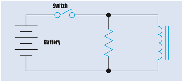
Refer to the circuit shown in Figure 14-21. Assume that the inductor has a wire resistance of 0.2
Expert Solution & Answer
Want to see the full answer?
Check out a sample textbook solution
Students have asked these similar questions
Refer to the circuit shown in Figure 14–21. Assume that the inductor has a wire resistance of 0.2 Ω and the resistor has a value of 250 Ω. If a current of 3 A is flowing through the inductor, what will be the maximum induced voltage when the switch is opened?
With V1, voltage peak to peak is 10 volts, R1=200 Ohm, R2=1000 Ohm and C1= 300 nF. Find Vx, voltage across the the capacitor, C1 and R2 when the frequency is 1000 Hz and 10000 Hz
There is an RL circuit with a switch 2-volt battery, a .15 H inductor, and a 60-ohm resistor. How long after the switch is closed would there be 10 milliamps in the circuit?
Chapter 14 Solutions
Mindtap Electrical, 4 Terms (24 Months) Printed Access Card For Herman's Delmar's Standard Textbook Of Electricity, 6th (mindtap Course List)
Ch. 14 - What determines the polarity of magnetism when...Ch. 14 - What determines the strength of the magnetic field...Ch. 14 - 3. Name three factors that determine the amount of...Ch. 14 - 4. How many lines of magnetic flux must be cut in...Ch. 14 - Prob. 5RQCh. 14 - Into how many time constants is an exponential...Ch. 14 - 7. Each time constant of an exponential curve is...Ch. 14 - 8. An inductor has an inductance of 0.025 H and a...Ch. 14 - Refer to the circuit shown in Figure 14-21. Assume...Ch. 14 - Prob. 10RQ
Knowledge Booster


Learn more about
Need a deep-dive on the concept behind this application? Look no further. Learn more about this topic, electrical-engineering and related others by exploring similar questions and additional content below.Similar questions
- A 5-ohm resistor is connected in series with a 25 micro-farad capacitor. A source voltage of 158 volts, 50 Hz supplies the combination. Determine the following: a. Circulating current b. Voltage across the resistor c. Voltage across the capacitorarrow_forwardElectrical Engineering I'm reading about the electronics in touch screen. It says when i touch the panel it distorts the electrostatic field and thus will have a change in capacitance. This is how it detects My question is the electrostatic field same as electric field? Please explain in details How did the capacitance change when i just touch the panelarrow_forwardWhen the voltage source is turned off in a simple circuit consists of a resistor and an inductor, the rate of decrease of the current is proportional to the current. The current is 40 amperes at the moment that the switch is off and dies down to 15 amperes after 0.01 sec. Determine the current in 0.02 sec. 3.375 amperes 4.25 amperes 5.625 amperes 6.025 amperesarrow_forward
- A capacitor of 1µF is charged to 100 volts and then disconnected from the power supply. A second but uncharged capacitor of 3µF is then connected across the first capacitor. What is the voltage across the parallel combination? O a. 110 volts O b. 45 volts O c. 66 volts O d. 25 voltsarrow_forwardIf a circuit has a resistance of 3002 and a series inductance of 5002, what is the relationship between the applied circuit voltage and the circuit current? The applied voltage lags the circuit current. The phase shift between the circuit voltage and current changes with time. The applied voltage is in phase with the circuit current. The applied voltage leads the circuit cur Previous Page Next Page Page 2 of 10arrow_forwardWhat is the current in the inductor ILO in continuity mode before opening the switch. R₁ Select one: O a. I = O b. I = E R₁ R₂ R₁+R₂ = E R₂ O c. I=0 O d. I E R₁ E k R₂ ILO Larrow_forward
- assume that tthe circuit shown in figure 21-1 is connected to a 480 v 60 hz line. the capcitor has a capacitance of 165.782 uf and the resistor has a resistance of 12 ohmas find the missing valuses.arrow_forwardFor the figure shown below if the current is moving clockwise around the coil. Which direction does the coil rotate? S O The whole coil moves down. The whole coil moves up. The right side goes down, and the left side goes up. The right side goes up, and the left side goes down.arrow_forwardCapacitor has the ability to store a quantity of a. Dynamic Electricity b. Dielectric c. Electric Flux O d. Static electricityarrow_forward
- Here are the choices: Lorentz law charge Faraday's law Ohm's law Capacitance Resistivity of materials Resistance vs Strainarrow_forwardIncandescent lighting of 500 W is connected in parallel with an inductive load. A clamp-on ammeter reveals a total circuit current of 7 A. What is the inductance of the load connected in parallel with the incandescent lights? Assume a voltage of 120 V and a frequency of 60 Hz.arrow_forwardA pure capacitive circuit is connected to a 480-volt, 60-Hz power source. An ammeter indicates a current flow of 24 amperes. The circuit current must be reduced to 16 amperes by connecting a second capacitor in series with the first. What is the value of the existing capacitor? What value capacitor should be connected in series with the original capacitor to limit the circuit current to 16 amperes?arrow_forward
arrow_back_ios
SEE MORE QUESTIONS
arrow_forward_ios
Recommended textbooks for you
 Delmar's Standard Textbook Of ElectricityElectrical EngineeringISBN:9781337900348Author:Stephen L. HermanPublisher:Cengage Learning
Delmar's Standard Textbook Of Electricity
Electrical Engineering
ISBN:9781337900348
Author:Stephen L. Herman
Publisher:Cengage Learning
02 - Sinusoidal AC Voltage Sources in Circuits, Part 1; Author: Math and Science;https://www.youtube.com/watch?v=8zMiIHVMfaw;License: Standard Youtube License