
Videos
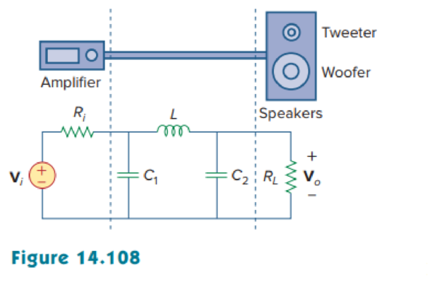
The crossover circuit in Fig. 14.108 is a low-pass filter that is connected to a woofer. Find the transfer function H(ω) = Vo(ω)/Vi(ω).
Find the transfer function
Answer to Problem 96P
The transfer function
Explanation of Solution
Given data:
Refer to Figure 14.108 in the textbook.
Formula used:
Write a general expression to calculate the impedance of resistor in s-domain.
Here,
Write a general expression to calculate the impedance of an inductor in s-domain.
Here,
Write a general expression to calculate the impedance of a capacitor in s-domain.
Here,
Write the general expression to calculate the transfer function of the system
Here,
Calculation:
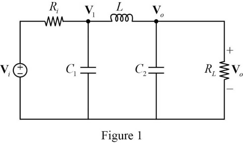
The given circuit is redrawn as Figure 1.
The s-domain circuit of the Figure 1 is drawn as Figure 2 using the equations (1), (2), and (3).
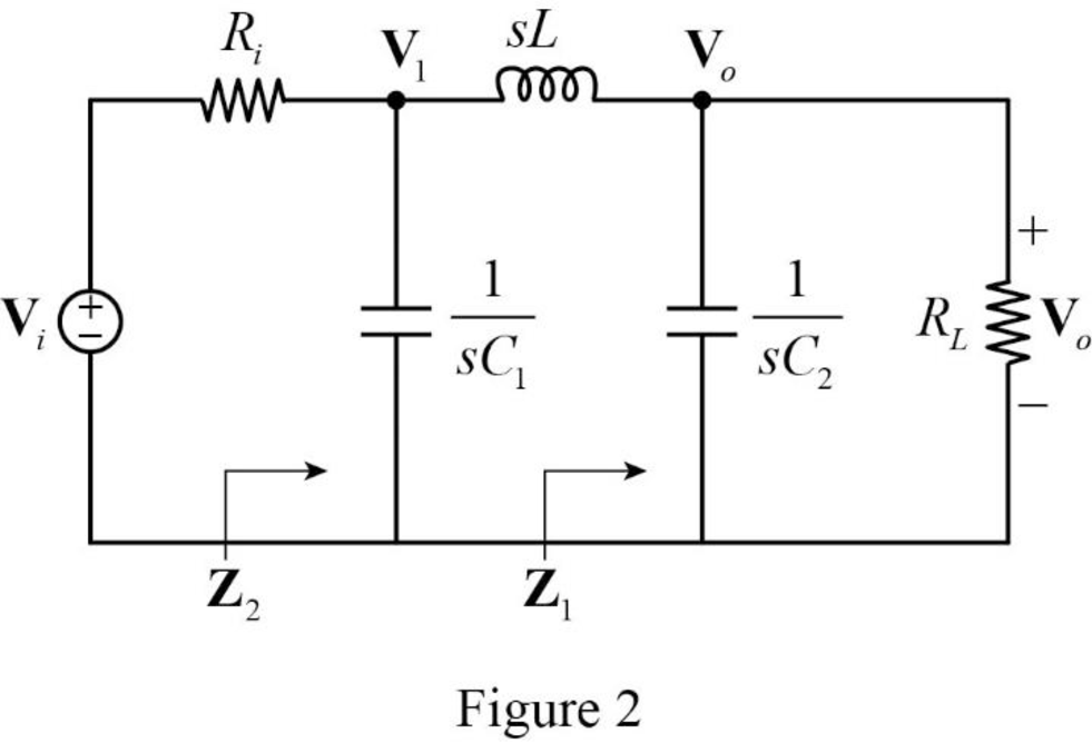
Refer to Figure 2, the resistor
The Figure 2 is redrawn as Figure 3.
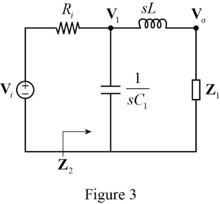
Refer to Figure 3, the inductor
Substitute
Simplify the above equation to find
The Figure 3 is redrawn as Figure 4.
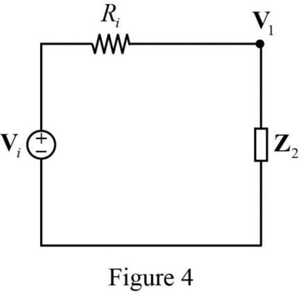
Apply voltage division rule on Figure 4 to find
Apply voltage division rule on Figure 3 to find
Substitute
Rearrange the above equation to find
Substitute
Simplify the above equation to find
Substitute
From the equation (5), the equation (4) becomes,
Conclusion:
Thus, the transfer function
Want to see more full solutions like this?
Chapter 14 Solutions
EBK FUNDAMENTALS OF ELECTRIC CIRCUITS


- Ims.mutah.edu.jo/mod, 0 The transfer function of the RC integrator circuit is given by Select one: 1/sC a. R+ 1/sC sC b. R + sC C. None R R+sC е. R+ 1/sCarrow_forwardLESSON: CONTROL SYSTEMS Obtain the transfer function Vo (s) / Vi (s) in terms of parameters for the electrical circuit given in the figure. Draw the Bode diagram of the expression you obtained by writing the values of R1 = 1 Kohm, R2 = 1 Kohm, C1 = 1nF, C2 = 1nF to the transfer function you found. R1 R2 Vin C1 C2 Vout NOTE: YOU CAN MAKE THE SOLUTIONS IN A DETAILED WAY!arrow_forwardApply the gain formula to the SFG shown in Figures land 2 to find the transfer function: ys/yıarrow_forward
- Design a bandpass filter using resistors and capacitors. You can select the values of R and C even, but the two crossover frequencies should be 6kHz and 40kHz.arrow_forwardSimplify the system into a single transfer function. SHOW COMPLETE SOLUTIONarrow_forwardA differentiating circuit has series connection of R=5ohms and C=0.25F connected to an input voltage (Vi). Find the transfer function Vo(s)/Vi(s) if Vo is measured across the resistor?arrow_forward
- Electrical Engineering Find the transfer function H(f) of the following circuit and sketch the Bode magnitude and phase plots: 5002 + Vout Vin 480 µFarrow_forward+0 in V 1.65 ΚΩ out a. Find the transfer function This is an active filter that is found on the RSLK project car. You may find the schematic at https://www.pololu.com/file/0J1670/ti-rslk-max-chassis-board-v1.0-schematic.pdf = f(w,R's,C's) V. out 18.2 ΚΩ V: 1 μF in 0.22 μF of this op amp circuit. + V:. b. Generate a standard Bode Plot (magnitude only) over 4 decades from 0.1 Hz to 1 KHz. NOTE: there is a lot of algebra in this problem. V outarrow_forwards+10 Q4- Draw the Bode Plot for the transfer function: s(s+5)2 mark on your plot the margins and crossover frequencies.arrow_forward
- O-- 5. What input voltage results in an output of 2 V in the circuit of Fig. 14.46? I MQ 20 ka Figure 14.46 Problem 5arrow_forwardMatlab Which command is used for plotting a bode plot in Matlab editor. Also give an example of bode plot.arrow_forwardElectrical Engineering Design a low-pass, high-pass, and band-pass filter based on the following schematic selecting your own values for components. Analyse the circuits in frequency iden- tifying center and cut-off frequencies. Build and verify the operation of the circuit based on the designs. V_L+ VC+ V_Lref V Cref VR+ 10.0mH 5.0µF Vin R1 5V Vout 500HZ 10.00 V Rrefarrow_forward
 Introductory Circuit Analysis (13th Edition)Electrical EngineeringISBN:9780133923605Author:Robert L. BoylestadPublisher:PEARSON
 Delmar's Standard Textbook Of ElectricityElectrical EngineeringISBN:9781337900348Author:Stephen L. HermanPublisher:Cengage Learning
 Programmable Logic ControllersElectrical EngineeringISBN:9780073373843Author:Frank D. PetruzellaPublisher:McGraw-Hill Education
 Fundamentals of Electric CircuitsElectrical EngineeringISBN:9780078028229Author:Charles K Alexander, Matthew SadikuPublisher:McGraw-Hill Education
 Electric Circuits. (11th Edition)Electrical EngineeringISBN:9780134746968Author:James W. Nilsson, Susan RiedelPublisher:PEARSON
 Engineering ElectromagneticsElectrical EngineeringISBN:9780078028151Author:Hayt, William H. (william Hart), Jr, BUCK, John A.Publisher:Mcgraw-hill Education,