
Concept explainers
Videos
Refer to the network in Fig. 14.96.
- (a) Find Zin(s).
- (b) Scale the elements by Km = 10 and Kf = 100. Find Zin(s) and ω0.
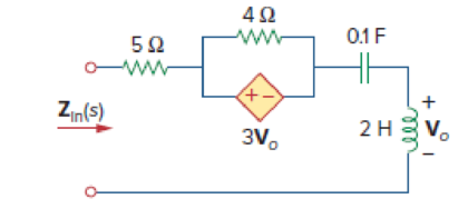
Figure 14.96
(a)
Find the value of the input impedance
Answer to Problem 79P
The value of the input impedance
Explanation of Solution
Given data:
Refer to Figure 14.96 in the textbook.
Formula used:
Write the expression to calculate the impedance of the passive elements resistor, inductor and capacitor in s-domain.
Here,
Calculation:
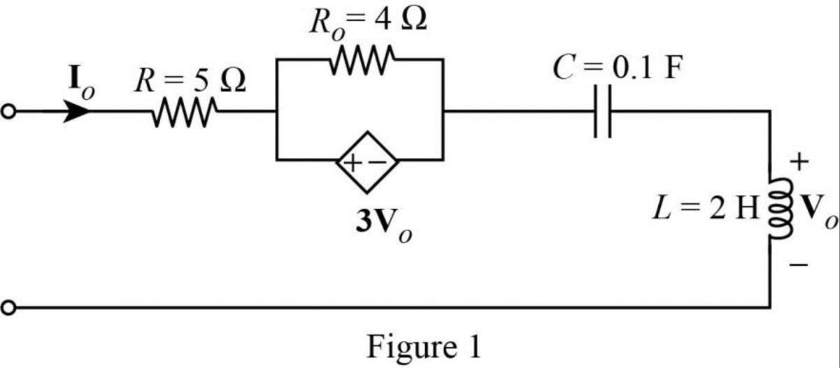
The given circuit is redrawn as Figure 1.
Use equation (1) to find
Use equation (1) to find
Use equation (2) to find
Use equation (3) to find
Insert a
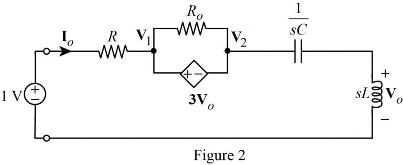
Modify the Figure 2 with the representation of supernode and current direction as shown in Figure 3.
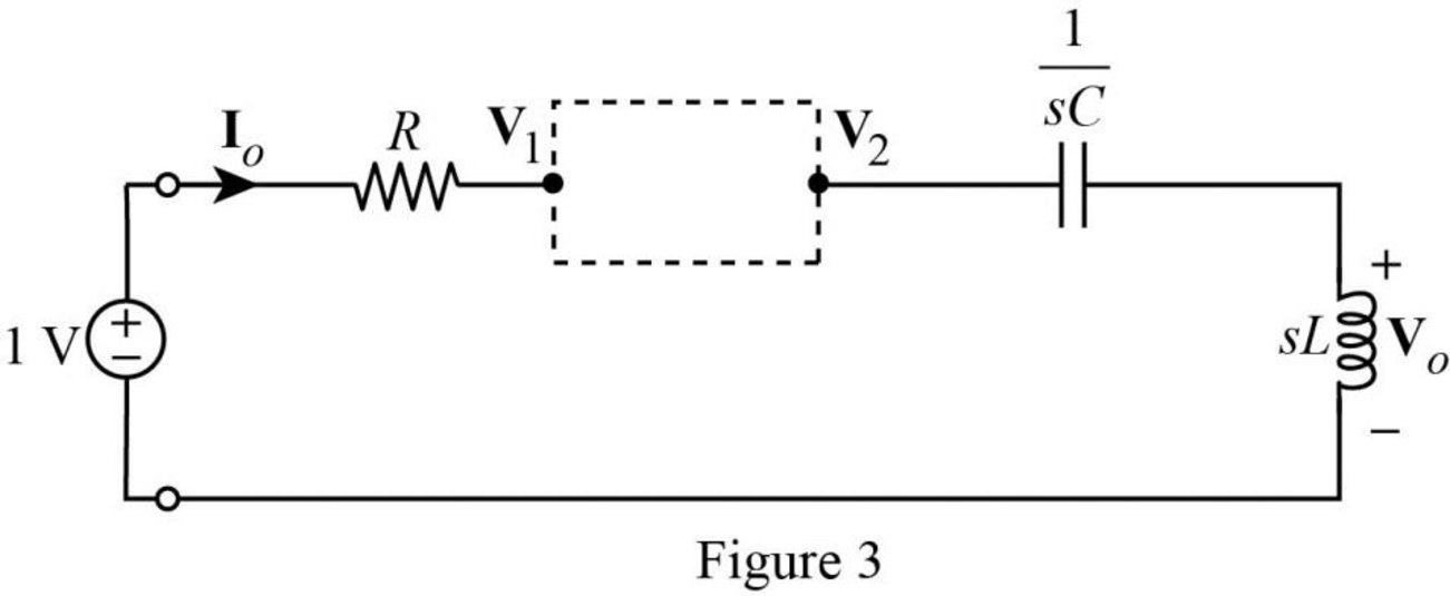
Apply Kirchhoff’s current law to the supernode in Figure 3.
The Figure 3 is reduced as following Figure 4 to show the voltage relation.
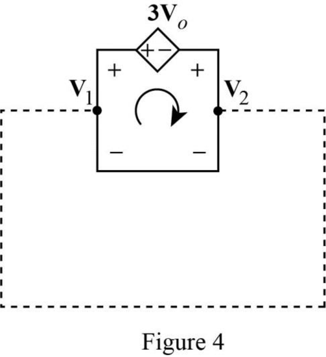
Apply Kirchhoff’s voltage law to the circuit in Figure 4 to obtain the relationship between voltages.
Apply voltage division rule on Figure 3 to find
Rearrange the above equation.
Rearrange the equation (6) to find
Substitute
Rearrange the above equation to find
Compare the equations (4) and (6) to obtain the following equation.
Substitute
Rearrange the above equation.
Simplify the above equation to find
Refer to Figure 3, the current
Substitute
The input impedance of the circuit in Figure 2 is calculated as follows.
Substitute
Substitute
Substitute
At resonance condition, the imaginary part of the impedance should be equal to zero. Therefore, equate the imaginary part of the above equation to zero.
Simplify the above equation to find
Take square root on both sides of the above equation to find
Substitute
Conclusion:
Thus, the value of the input impedance
(b)
Find the value of the input impedance
Answer to Problem 79P
The value of the input impedance
Explanation of Solution
Given data:
The value of the magnitude scaling factor
The value of the frequency scaling factor
Formula used:
Consider the equations used in magnitude and frequency scaling.
Write the expression to calculate the scaled resistor.
Here,
Write the expression to calculate the scaled inductor.
Here,
Write the expression to calculate the scaled capacitor.
Calculation:
Substitute
Substitute
Substitute
Substitute
Substitute
Conclusion:
Thus, the value of the input impedance
Want to see more full solutions like this?
Chapter 14 Solutions
EBK FUNDAMENTALS OF ELECTRIC CIRCUITS


- 12- Self commutated circuit drawn 200A maximum from 200 V source voltage. Find the value of the inductance if the ringing frequency is 2000 rad/s * L=1mH L=0.5 mH L=24 mHarrow_forwardGiven the following circuit diagram, where the impedances are R = 3 Q, C = -j10 Q & L = j8 0. The voltage source is 4*cos(1000nt + -90°)V. Find the voltage across the inductor (VL), in polar form accurate to within 1% and 2⁰. vs(t) VL = R HH Hi ww °Varrow_forwardAntenna Tank Circuit L Germanium Amplifier Diode To Speakers 12 pF - 120 pF Vout 100 ka R2 RI { Low Pass Filter Figure 4 Figure 4 shows a radio receiver circuit. The antenna that receives radio signals can be modelled as an AC current source, I.. The antenna is connected to a "Tank Circuit" that consist of an inductor with inductance L, and a variable capacitor, and then connected to the ground. When the capacitor is tuncd to the right value, a very high voltage Vo is generated to send signals through the Germanium diode, and the signals are passed into an amplifier system and then converted to sound in the speakers. If the inductance L is given as 1.0 miero-Henries, determine the capacitance values (in pico- Farads) to tune to your favourite Radio Stations in Malaysia listed in the table below: Radio Station Frequency, Angular Tuned Name f Frequency, o Capacitance, pF 988 FM Best FM 98.8 MHz 104.1 MHz Mutiara FM 95.7 MHz Nasional FM 88.5 MHzarrow_forward
- obtain Z-trans form for the Following XC+)= sin (t - 3T)arrow_forwardFor the following RLC circuit if L = 6.7 mH and Vc is shown in the figure below. Assuming ideal components the value of R (in Ohms) is about: Tek I Trig'd M Pos: 228.0s AUTOSET CH1 Mean 475mV Undo Autoset CHI 200m CH1/0.00V M 50.0 1-Dec-10 196 287.783Hz a. 0.07 O b. 67.00 O c. 2.30 d. 103.18 O e. 148.89arrow_forwardIn the given RLC network, Vxy = Yyz 50V and current which is flowing in the network is 2A. The value of inductance in the given circuit is R ww- C L 2A 50V, 50HZ O 31.8 mH O 0.62 H O 0.159 H 6.2 mHarrow_forward
- The impedance of a series combination of a 10 resistor, a 10 capacitor, and a 10 inductor is a. 14.14 450 b. 14.14 -450 c. 10 90o d. 10 0oarrow_forwardS C R find the mathematical model of the system when the switch is in position 1 and in position 2 find the natural frequency of the circuit when the switch is in position 2 Obtain a mechanical system analogous to the electrical system shown when the switch is in position 1 R=121 0 L=61mH C=36µFarrow_forwardDetermine if each statement is True or False; if false, please explain whya) A forced oscillator is when a system is being yelled at to perform a specific motion.b) Impedance is a measure of the total resistance a RLC series circuit has towards current.c) The phase angle tells us how “out-of-phase” the charge on the capacitor iswith the driving voltage.arrow_forward
- Q1 Find equivalent circuit in frequency domain for the circuit below Find the current across 650mh inductor C₁ 4.7 μF L650 mH 120 V 60 Hz R 4702 C₂ 1.5 µF Example series-parallel R, L, and C circuit.arrow_forwardIn a series RLC circuit, R= 15 ohm, L= 20mH, C=100UF is connected to an ac voltage 169.7V , 60HZ, then the total current in the circuit is Select one: a. None of these b. 4.5<-26.3 c. 6.56<8.96 d. 4.96<51.71arrow_forwardAn inductor with L = 150mH and r = 200(Omega) is in series with a capacitor, a resistor, and a generator of w = 1000 rad / s The voltage across the inductor Vind is measured to be 10.87 V, VR is measured to be 4.65 , and Vc is measured to be 5.96 V. What is the generator voltage V? (Hint: This is the measurement to be performed in this laboratory for LCR circuits. Use the appropriate equations to find VL and Vr' and then use them and the values of VR and VC to calculate V.)arrow_forward
 Delmar's Standard Textbook Of ElectricityElectrical EngineeringISBN:9781337900348Author:Stephen L. HermanPublisher:Cengage Learning