
Loose Leaf for Engineering Circuit Analysis Format: Loose-leaf
9th Edition
ISBN: 9781259989452
Author: Hayt
Publisher: Mcgraw Hill Publishers
expand_more
expand_more
format_list_bulleted
Videos
Textbook Question
Chapter 14, Problem 65E
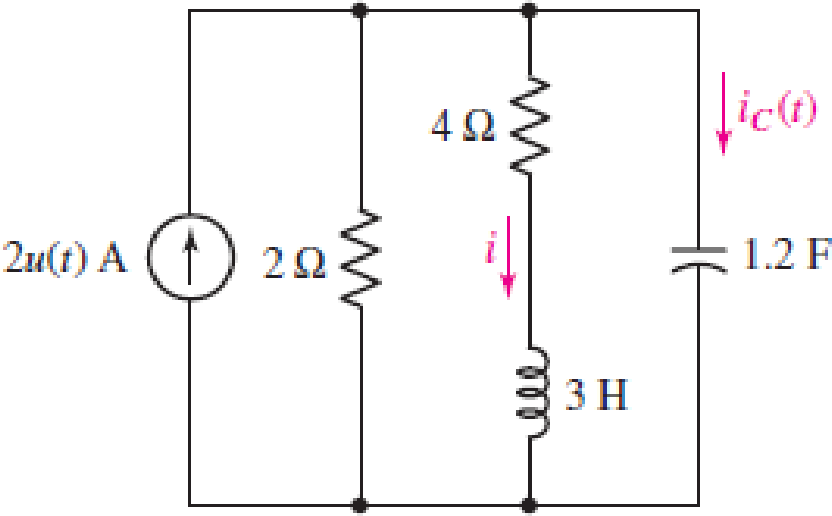
For the circuit shown in Fig. 14.62, determine the s-domain Thévenin equivalent seen by the (a) 2 Ω resistor; (b) 4 Ω resistor; (c) 1.2 F capacitor; (d) current source.
Expert Solution & Answer
Want to see the full answer?
Check out a sample textbook solution
Students have asked these similar questions
Handwritten solution required do not use chatgpt
A conductor 300 mm long carries a current of 13A and is at right-angles to a magnetic fieldbetween two circular pole faces, each of diameter 80 mm. If the total flux between the polefaces is 0.75 mWb, calculate the force exerted on the conductor. [ANS = 0.582 N]
a) find Rthb) Find Vth in the circuit
c)Draw the Thevenin Equivalent of the circuit to tge left of the a and b terminals
Chapter 14 Solutions
Loose Leaf for Engineering Circuit Analysis Format: Loose-leaf
Ch. 14.1 - Identify all the complex frequencies present in...Ch. 14.1 - Use real constants A, B, C, , and so forth, to...Ch. 14.2 - Let f (t) = 6e2t [u(t + 3) u(t 2)]. Find the (a)...Ch. 14.3 - Prob. 4PCh. 14.3 - Prob. 5PCh. 14.4 - Prob. 6PCh. 14.4 - Prob. 7PCh. 14.4 - Prob. 8PCh. 14.4 - Prob. 9PCh. 14.5 - Prob. 10P
Ch. 14.5 - Prob. 11PCh. 14.5 - Prob. 12PCh. 14.6 - Prob. 13PCh. 14.7 - Prob. 14PCh. 14.7 - Prob. 15PCh. 14.8 - Find the mesh currents i1 and i2 in the circuit of...Ch. 14.8 - Prob. 17PCh. 14.8 - Prob. 18PCh. 14.9 - Using the method of source transformation, reduce...Ch. 14.9 - Prob. 20PCh. 14.10 - The parallel combination of 0.25 mH and 5 is in...Ch. 14.11 - Prob. 22PCh. 14.11 - Prob. 23PCh. 14.11 - Prob. 24PCh. 14.11 - Prob. 25PCh. 14.12 - Prob. 26PCh. 14 - Determine the conjugate of each of the following:...Ch. 14 - Compute the complex conjugate of each of the...Ch. 14 - Several real voltages are written down on a piece...Ch. 14 - State the complex frequency or frequencies...Ch. 14 - For each of the following functions, determine the...Ch. 14 - Use real constants A, B, , , etc. to construct the...Ch. 14 - The following voltage sources AeBt cos(Ct + ) are...Ch. 14 - Prob. 8ECh. 14 - Compute the real part of each of the following...Ch. 14 - Your new assistant has measured the signal coming...Ch. 14 - Prob. 11ECh. 14 - Prob. 12ECh. 14 - Prob. 13ECh. 14 - Prob. 14ECh. 14 - Prob. 15ECh. 14 - Prob. 16ECh. 14 - Determine F(s) if f (t) is equal to (a) 3u(t 2);...Ch. 14 - Prob. 18ECh. 14 - Prob. 19ECh. 14 - Prob. 20ECh. 14 - Prob. 21ECh. 14 - Evaluate the following: (a)[(2t)]2 at t = 1;...Ch. 14 - Evaluate the following expressions at t = 0: (a)...Ch. 14 - Prob. 24ECh. 14 - Prob. 25ECh. 14 - Prob. 26ECh. 14 - Prob. 27ECh. 14 - Prob. 28ECh. 14 - Prob. 29ECh. 14 - Prob. 30ECh. 14 - Prob. 31ECh. 14 - Prob. 32ECh. 14 - Prob. 33ECh. 14 - Obtain the time-domain expression which...Ch. 14 - Prob. 35ECh. 14 - Prob. 36ECh. 14 - Prob. 37ECh. 14 - Prob. 38ECh. 14 - Prob. 39ECh. 14 - Prob. 40ECh. 14 - Prob. 41ECh. 14 - Obtain, through purely legitimate means, an...Ch. 14 - Prob. 43ECh. 14 - Employ the initial-value theorem to determine the...Ch. 14 - Prob. 45ECh. 14 - Prob. 46ECh. 14 - Prob. 47ECh. 14 - Prob. 48ECh. 14 - Prob. 49ECh. 14 - Prob. 52ECh. 14 - Determine v(t) for t 0 for the circuit shown in...Ch. 14 - Prob. 54ECh. 14 - Prob. 55ECh. 14 - For the circuit of Fig. 14.54, (a) draw both...Ch. 14 - Prob. 58ECh. 14 - Prob. 59ECh. 14 - Prob. 60ECh. 14 - For the circuit shown in Fig. 14.58, let is1 =...Ch. 14 - Prob. 63ECh. 14 - Prob. 64ECh. 14 - For the circuit shown in Fig. 14.62, determine the...Ch. 14 - Prob. 67ECh. 14 - Prob. 68ECh. 14 - Determine the poles and zeros of the following...Ch. 14 - Use appropriate means to ascertain the poles and...Ch. 14 - Prob. 71ECh. 14 - For the network represented schematically in Fig....Ch. 14 - Prob. 73ECh. 14 - Prob. 74ECh. 14 - Prob. 75ECh. 14 - Prob. 76ECh. 14 - Prob. 77ECh. 14 - Prob. 78ECh. 14 - Prob. 79ECh. 14 - Prob. 80ECh. 14 - Prob. 81ECh. 14 - Prob. 82ECh. 14 - Design a circuit which produces the transfer...Ch. 14 - Prob. 84ECh. 14 - Prob. 85ECh. 14 - An easy way to get somebodys attention is to use a...Ch. 14 - Prob. 87E
Additional Engineering Textbook Solutions
Find more solutions based on key concepts
Why is the study of database technology important?
Database Concepts (8th Edition)
This optional Google account security feature sends you a message with a code that you must enter, in addition ...
SURVEY OF OPERATING SYSTEMS
What types of polymers are most commonly blow molded?
Degarmo's Materials And Processes In Manufacturing
What is an uninitialized variable?
Starting Out with Programming Logic and Design (5th Edition) (What's New in Computer Science)
1.2 Explain the difference between geodetic and plane
surveys,
Elementary Surveying: An Introduction To Geomatics (15th Edition)
The job of the _____ is to fetch instructions, carry out the operations commanded by the instructions, and prod...
Starting Out With Visual Basic (8th Edition)
Knowledge Booster


Learn more about
Need a deep-dive on the concept behind this application? Look no further. Learn more about this topic, electrical-engineering and related others by exploring similar questions and additional content below.Similar questions
- An electric car runs on batteries, but needs to make constant stops to re-charge. If a trailer is attached to the car that carries a generator, and the generator is turned by a belt attached to the wheels of the trailer, will the car be able to drive forever without stopping?arrow_forwardA singl core cable of voltage 30 kv. The diameter of Conductor is 3 cm. The diameter of cable is 25 cm. This cable has Two layer of insulator having arelative permittivity 5-3 respectively of The ratio of maximum electric stress of maximum electric stress 8 First layer to the of second layer is 10 Find & 1- The thickness of each layers. 3- The voltage of each layers. §. Layers The saving in radius of cable if another ungrading cable has the Same maximum electric stress, Total village, Conductor diameter of grading cable.arrow_forward66 KV sing care Cable has a drameter of conductor of 3 cm. The radius of cable is 10 cm. This Cable house Two relative permmitivity of insulation 6 and 4 respectively. If The ratio of maximum electric stress of first layer to the maximum eledric streep & second layer is s 1- find the village & each layers. 2- Min- electric stress J Cable 3- Compare the voltage of ungrading Cable has the same distance and relectric stresses.arrow_forward
- Prelab Information 1. Laboratory Preliminary Discussion First-order Low-pass RC Filter Analysis The first-order low-pass RC filter shown in figure 1 below represents all voltages and currents in the time domain. It is of course possible to solve for all circuit voltages using time domain differential equation techniques, but it is more efficient to convert the circuit to its s-domain equivalent as shown in figure 2 and apply Laplace transform techniques. vs(t) i₁(t) + R₁ ww V₁(t) 12(t) Lic(t) Vout(t) = V2(t) R₂ Vc(t) C Vc(t) VR2(t) = V2(t) + Vs(s) Figure 1: A first-order low-pass RC filter represented in the time domain. I₁(s) R1 W + V₁(s) V₂(s) 12(s) Ic(s) + Vout(S) == Vc(s) Vc(s) Zc(s) = = VR2(S) V2(s) Figure 2: A first-order low-pass RC filter represented in the s-domain.arrow_forwarduse matlabarrow_forwardI need help with this problem and an explanation of the solution for the image described below. (Introduction to Signals and Systems)arrow_forward
- How do we know that D1 is forward bias and D2 is reverse biased?arrow_forwardSolve it in a different way than the previous solution that I searched forarrow_forwardA lossless uncharged transmission line of length L = 0.45 cm has a characteristic impedance of 60 ohms. It is driven by an ideal voltage generator producing a pulse of amplitude 10V and width 2 nS. If the transmission line is connected to a load of 200 ohms, sketch the voltage at the load as a function of time for the interval 0 < t < 20 nS. You may assume that the propagation velocity of the transmission is c/2. Answered now answer number 2. Repeat Q.1 but now assume the width of the pulse produced by the generator is 4 nS. Sketch the voltage at the load as a function of time for 0 < t < 20 nS.arrow_forward
- Solve this experiment with an accurate solution, please. Thank you.arrow_forwardA lossless uncharged transmission line of characteristic impedance Zo = 600 and length T = 1us is connected to a 180 load. If this transmission line is connected at t = 0 to a 90 V dc source with an internal resistance of 900, from a bounce diagram of this system sketch (a) the voltage at z=0, z=L, and z = L/2 for up to 7.25μs and (b) calculate the load voltage after an infinite amount of time.arrow_forwardA lossless uncharged transmission line of length L = 0.45 cm has a characteristic impedance of 60 ohms. It is driven by an ideal voltage generator producing a pulse of amplitude 10V and width 2 nS. If the transmission line is connected to a load of 200 ohms, sketch the voltage at the load as a function of time for the interval 0 < t < 20 nS. You may assume that the propagation velocity of the transmission is c/2.arrow_forward
arrow_back_ios
SEE MORE QUESTIONS
arrow_forward_ios
Recommended textbooks for you
 Introductory Circuit Analysis (13th Edition)Electrical EngineeringISBN:9780133923605Author:Robert L. BoylestadPublisher:PEARSON
 Delmar's Standard Textbook Of ElectricityElectrical EngineeringISBN:9781337900348Author:Stephen L. HermanPublisher:Cengage Learning
 Programmable Logic ControllersElectrical EngineeringISBN:9780073373843Author:Frank D. PetruzellaPublisher:McGraw-Hill Education
 Fundamentals of Electric CircuitsElectrical EngineeringISBN:9780078028229Author:Charles K Alexander, Matthew SadikuPublisher:McGraw-Hill Education
 Electric Circuits. (11th Edition)Electrical EngineeringISBN:9780134746968Author:James W. Nilsson, Susan RiedelPublisher:PEARSON
 Engineering ElectromagneticsElectrical EngineeringISBN:9780078028151Author:Hayt, William H. (william Hart), Jr, BUCK, John A.Publisher:Mcgraw-hill Education,
Introductory Circuit Analysis (13th Edition)
Electrical Engineering
ISBN:9780133923605
Author:Robert L. Boylestad
Publisher:PEARSON
Delmar's Standard Textbook Of Electricity
Electrical Engineering
ISBN:9781337900348
Author:Stephen L. Herman
Publisher:Cengage Learning
Programmable Logic Controllers
Electrical Engineering
ISBN:9780073373843
Author:Frank D. Petruzella
Publisher:McGraw-Hill Education
Fundamentals of Electric Circuits
Electrical Engineering
ISBN:9780078028229
Author:Charles K Alexander, Matthew Sadiku
Publisher:McGraw-Hill Education
Electric Circuits. (11th Edition)
Electrical Engineering
ISBN:9780134746968
Author:James W. Nilsson, Susan Riedel
Publisher:PEARSON
Engineering Electromagnetics
Electrical Engineering
ISBN:9780078028151
Author:Hayt, William H. (william Hart), Jr, BUCK, John A.
Publisher:Mcgraw-hill Education,
L21E127 Control Systems Lecture 21 Exercise 127: State-space model of an electric circuit; Author: bioMechatronics Lab;https://www.youtube.com/watch?v=sL0LtyfNYkM;License: Standard Youtube License