University Physics Volume 2
18th Edition
ISBN: 9781938168161
Author: OpenStax
Publisher: OpenStax
expand_more
expand_more
format_list_bulleted
Textbook Question
Chapter 14, Problem 58P
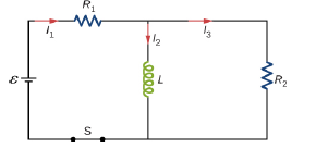
Consider the circuit shown below. Find l1, l2and l3when (a) the switch S is first closed, (b) after the currents have reached steady-state values, and (c) at the instant the switch is reopened (after being closed for a long time).

Expert Solution & Answer
Want to see the full answer?
Check out a sample textbook solution
Students have asked these similar questions
19:39 ·
C
Chegg
1 69%
✓
The compound beam is fixed at Ę and supported by rollers at A and B. There are pins at C and D. Take
F=1700 lb. (Figure 1)
Figure
800 lb
||-5-
F
600 lb
بتا
D
E
C
BO
10 ft 5 ft 4 ft-—— 6 ft — 5 ft-
Solved Part A The compound
beam is fixed at E and...
Hình ảnh có thể có bản quyền. Tìm hiểu thêm
Problem
A-12
% Chia sẻ
kip
800 lb
Truy cập )
D Lưu
of
C
600 lb
|-sa+ 10ft 5ft 4ft6ft
D
E
5 ft-
Trying
Cheaa
Những kết quả này có
hữu ích không?
There are pins at C and D To F-1200 Egue!)
Chegg
Solved The compound b...
Có Không ☑
|||
Chegg
10
וח
No chatgpt pls will upvote
No chatgpt pls will upvote
Chapter 14 Solutions
University Physics Volume 2
Ch. 14 - Check Your Understanding. A current...Ch. 14 - Check Your Understanding. Current flows through...Ch. 14 - Check Your Understanding. A changing current...Ch. 14 - Check Your Understanding (a) Calculate the...Ch. 14 - Check Your Understanding (a) What is the magnetic...Ch. 14 - Check Your Understanding How much energy is stored...Ch. 14 - Check Your Understanding Verify that RC and L/R...Ch. 14 - Check Your Understanding (a) If the current in the...Ch. 14 - Check Your Understanding For the circuit of in...Ch. 14 - Check Your Understanding The angular frequency of...
Ch. 14 - Check Your Understanding In an RLC circuit, L =...Ch. 14 - Show that N m /l and el(dl/dt), which are both...Ch. 14 - A 10-H inductor carries a current of 20 A....Ch. 14 - The ignition circuit of an automobile is powered...Ch. 14 - When the current through a large inductor is...Ch. 14 - Does self-inductance depend on the value of the...Ch. 14 - Would the self-inductance of a 1.0 m long, tightly...Ch. 14 - Discuss how you might determine the-inductance per...Ch. 14 - The self-inductance of a coil is zero if there is...Ch. 14 - How does the self- inductance per unit length near...Ch. 14 - Solve that I I 2 /2 has units of energy.Ch. 14 - Use Lenz’s law to explain why the initial current...Ch. 14 - When the current in the RL circuit of Figure...Ch. 14 - Does the time required for the current in an RL...Ch. 14 - An inductor is connected across the terminals of a...Ch. 14 - At what time is the voltage across the inductor of...Ch. 14 - In the simple RL circuit of Figure 14.12(b), can...Ch. 14 - If emf of the battery of Figure 14.12(b) is...Ch. 14 - A steady current flows through a circuit with a...Ch. 14 - Describe how the currents through R1and R2, shown...Ch. 14 - Discuss possible practical applications of RL...Ch. 14 - Do Kirchhoff’s rules apply to circuits that...Ch. 14 - Can a circuit e1eent have both capacitance and...Ch. 14 - In an LC circuit, what determines the frequency...Ch. 14 - When a wire is connected between the two ends of a...Ch. 14 - Describe what effect the resistance of the...Ch. 14 - Suppose you wanted to design an LC circuit with a...Ch. 14 - A radio receiver uses an RLC circuit to pick out...Ch. 14 - When the current in one coi1 changes at a rate of...Ch. 14 - An emf of 9.7 × 10⁻³ V is induced in a coil while...Ch. 14 - Two coils close to each other have a mutual...Ch. 14 - A coil of 40 turns is wrapped around a long...Ch. 14 - A 600-turn solenoid is 0.55 m long and 4.2 cm in...Ch. 14 - A toroidal coil has a mean radius of 16 cm and a...Ch. 14 - A solenoid of N1turns has length l1and radius R1,...Ch. 14 - An emf of 0.40 V is induced across a coil when the...Ch. 14 - The current shown in part (a) below is increasing,...Ch. 14 - What is the rate at which the current though a...Ch. 14 - When a camera uses a flash, a fully charged...Ch. 14 - A coil with a self-inductance of 2.0 H carries a...Ch. 14 - A solenoid 50 cm long is wound with 500 turns of...Ch. 14 - A coil with a self-inductance of 3.0 H carries a...Ch. 14 - The current I(t) through a 5.0-mH inductor varies...Ch. 14 - A long, cylindrical solenoid with 100 turns per...Ch. 14 - Suppose that a rectangular toroid has 2000...Ch. 14 - What is the self-inductance per meter of a coaxial...Ch. 14 - At the instant a current of 0.20 A is flowing...Ch. 14 - Suppose that a rectangular toroid has 2000...Ch. 14 - Solenoid A is tightly wound while solenoid B has...Ch. 14 - A 10-H inductor carries a current of 20 A. How...Ch. 14 - A coil with a self-inductance of 3.0 H and a...Ch. 14 - A current of 1.2 A is flowing in a coaxial cable...Ch. 14 - In Figure 14.12, =12V , L = 20 mH, and R=5.0....Ch. 14 - For the circuit shown below, =20V , L = 4.0 mH,...Ch. 14 - The current in the RL circuit shown here increases...Ch. 14 - How long after switch S1 is thrown does it take...Ch. 14 - Examine the circuit shown below in part (a)....Ch. 14 - The current in the RL circuit shown below reaches...Ch. 14 - Consider the circuit shown below. Find l1, l2and...Ch. 14 - For the circuit shown below, =50V , R1= 10 , and...Ch. 14 - For the circuit shown below, find the current...Ch. 14 - Show that for the circuit shown below, the initial...Ch. 14 - A 5000-pF capacitor is charged to 100 V and then...Ch. 14 - The self-inductance and capacitance of an LC...Ch. 14 - What is the self-inductance of an LC circuit that...Ch. 14 - In an oscillating LC circuit the maximum charge on...Ch. 14 - The self-inductance and capacitance of an...Ch. 14 - In an oscillating LC circuit, the maximum charge...Ch. 14 - In the circuit shown below, S1is opened and S2is...Ch. 14 - An LC circuit in an AM tuner (in a car stereo)...Ch. 14 - In an oscillating RLC circuit, R=5.0 ,. L=5.0mH ,...Ch. 14 - In an oscillating RLC circuit with L = 10 mH, C =...Ch. 14 - What resistance R must be connected in series with...Ch. 14 - Show that the self-inductance per unit length of...Ch. 14 - Two long, parallel wires cy equal currents in...Ch. 14 - A small, rectangular single loop of wire with...Ch. 14 - Suppose that a cylindrical solenoid is wrapped...Ch. 14 - A solenoid with 4 x 10⁷turns/m has an iron core...Ch. 14 - A rectangular toroid with inner radius R1= 7.0cm,...Ch. 14 - The switch S of the circuit shown below is closed...Ch. 14 - In an oscillating RLC circuit, R = 7.0 L. = 10...Ch. 14 - A 25.0-H inductor has 100 A of current turned off...Ch. 14 - A coaxial cable has an inner conductor of radius...Ch. 14 - In a damped oscillating circuit the energy is...Ch. 14 - The switch in the circuit shown below is closed at...Ch. 14 - A square loop of side 2 cm is placed 1 cm from a...Ch. 14 - A rectangular copper ring, of mass 100 g and...
Additional Science Textbook Solutions
Find more solutions based on key concepts
The structural formulas for the given molecules need to be drawn. The mirror images of each molecule need to be...
Living By Chemistry: First Edition Textbook
Draw the mechanism for the hydroxide ion-catalyzed cleavage of fructose-l.6-bisphosphate.
Organic Chemistry (8th Edition)
Calculate the molarity of each solution. a. 22.6 g of C12H22O11 in 0.442 L of solution b. 42.6 g of NaCl in 1.5...
Introductory Chemistry (6th Edition)
Fill in the blanks: The nose is to the mouth. The ankle is to the knee. The ring finger is to the inde...
Human Anatomy & Physiology (2nd Edition)
10.71 Identify each of the following as an acid or a base: (10.1)
H2SO4
RbOH
Ca(OH)2
HI
...
Chemistry: An Introduction to General, Organic, and Biological Chemistry (13th Edition)
Name the components (including muscles) of the thoracic cage. List the contents of the thorax.
Human Physiology: An Integrated Approach (8th Edition)
Knowledge Booster
Learn more about
Need a deep-dive on the concept behind this application? Look no further. Learn more about this topic, physics and related others by exploring similar questions and additional content below.Similar questions
- No chatgpt pls will upvotearrow_forwardair is pushed steadily though a forced air pipe at a steady speed of 4.0 m/s. the pipe measures 56 cm by 22 cm. how fast will air move though a narrower portion of the pipe that is also rectangular and measures 32 cm by 22 cmarrow_forwardNo chatgpt pls will upvotearrow_forward
- 13.87 ... Interplanetary Navigation. The most efficient way to send a spacecraft from the earth to another planet is by using a Hohmann transfer orbit (Fig. P13.87). If the orbits of the departure and destination planets are circular, the Hohmann transfer orbit is an elliptical orbit whose perihelion and aphelion are tangent to the orbits of the two planets. The rockets are fired briefly at the depar- ture planet to put the spacecraft into the transfer orbit; the spacecraft then coasts until it reaches the destination planet. The rockets are then fired again to put the spacecraft into the same orbit about the sun as the destination planet. (a) For a flight from earth to Mars, in what direction must the rockets be fired at the earth and at Mars: in the direction of motion, or opposite the direction of motion? What about for a flight from Mars to the earth? (b) How long does a one- way trip from the the earth to Mars take, between the firings of the rockets? (c) To reach Mars from the…arrow_forwardNo chatgpt pls will upvotearrow_forwarda cubic foot of argon at 20 degrees celsius is isentropically compressed from 1 atm to 425 KPa. What is the new temperature and density?arrow_forward
- Calculate the variance of the calculated accelerations. The free fall height was 1753 mm. The measured release and catch times were: 222.22 800.00 61.11 641.67 0.00 588.89 11.11 588.89 8.33 588.89 11.11 588.89 5.56 586.11 2.78 583.33 Give in the answer window the calculated repeated experiment variance in m/s2.arrow_forwardNo chatgpt pls will upvotearrow_forwardCan you help me solve the questions pleasearrow_forward
- Can you help me solve these questions please so i can see how to do itarrow_forwardHow can i solve this if n1 (refractive index of gas) and n2 (refractive index of plastic) is not known. And the brewsters angle isn't knownarrow_forward2. Consider the situation described in problem 1 where light emerges horizontally from ground level. Take k = 0.0020 m' and no = 1.0001 and find at which horizontal distance, x, the ray reaches a height of y = 1.5 m.arrow_forward
arrow_back_ios
SEE MORE QUESTIONS
arrow_forward_ios
Recommended textbooks for you

What is Electromagnetic Induction? | Faraday's Laws and Lenz Law | iKen | iKen Edu | iKen App; Author: Iken Edu;https://www.youtube.com/watch?v=3HyORmBip-w;License: Standard YouTube License, CC-BY