
Concept explainers
Videos
Let N1 = 1000 turns and N2 = 5000 turns in the ideal transformer shown in Fig. 13.34. If ZL = 500 − j400 Ω, find the average power delivered to ZL for (a)
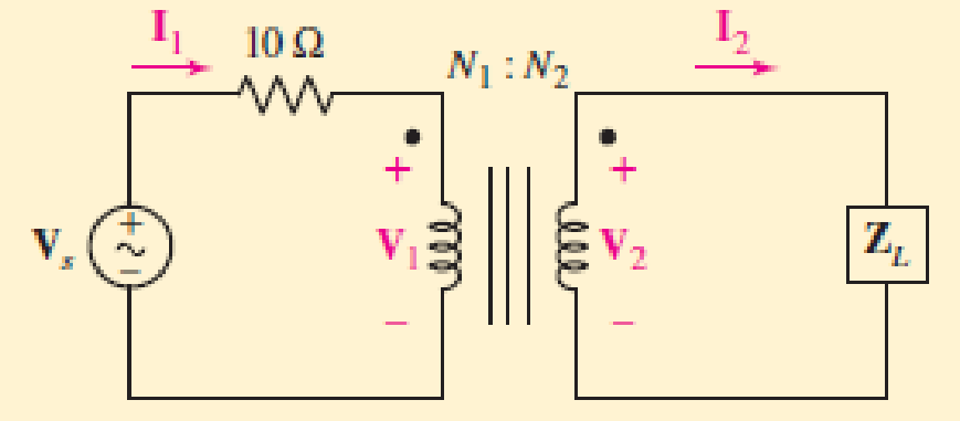
■ FIGURE 13.34
Want to see the full answer?
Check out a sample textbook solution
Chapter 13 Solutions
ENGINEERING CIRCUIT...(LL)>CUSTOM PKG.<
Additional Engineering Textbook Solutions
Electrical Engineering: Principles & Applications (7th Edition)
Electric Motors and Control Systems
Fundamentals of Applied Electromagnetics (7th Edition)
Basic Engineering Circuit Analysis
Electric machinery fundamentals
Electric Circuits. (11th Edition)


- A 100kVA transformer has a maximum efficiency of 0.95 at 50% full load and unity power factor . During a day , it is loaded as follows : 100kVA at unity p.f for 8hours , 50kVA at 0.8p.f. for 6hours, and no load for 10hours. Determine its all day efficiency .arrow_forwardIn the circuit shown below, the transformer is driven by a source with an open circuit voltage Vs of 120 V (rms) and an internal impedance Zs of 6 22. The frequency of the source is 200 rad/sec. The transformer drives a load consisting of a 60 n resistor. The transformer parameters are: R₁ = 12 Q2, R2 = 24 2, L₁ = 30 mH, L2 = 120 mH and k = 0.9. L1 Determine the currents /1 and /2 and the power delivered to the load. Vs Zs I₁ a b R₁ M L₁ M L₂ R₂ m d 1₂ N ZLarrow_forward8. The circuit below is similar to Problem 7 and operates at a frequency of 10 kHz. Circuit element Z can be either a capacitor or inductor. Assuming the transformer is ideal, determine the inductance or capacitance of Z and the turns ratio N that optimizes the power delivered to the load, RL , then calculate the power in R1. 1:N k 10490° R= 200 2 -j4 2 =arrow_forward
- Q1: The primary of a certain transformer takes 0.7 A at a power factor of 0.5 when it is connected across 200 V, 50 Hz supply and the secondary is on open circuit. The number of turns on the primary is twice that on the secondary. A load taking 10 A at a lagging power factor of 0.8 is now connected across the secondary. Calculate the primary current and power factor. Draw the phasor diagram.arrow_forwardA star connected load with real impedance ZL= 1-j1 Ohm per phase is connected to the secondary of a three-phase Ynyn0 connected transformer. The equivalent impedance per reduced phase of the transformer to the primary is Zeq1= 1+j5 Ohm. The nominal primary voltage is V1Ln= 5920 V and the conversion ratio is a= 10. what is the amplitude of the actual voltage falling on one phase of the specified load? (simplified equivalent circuit will be used).arrow_forwardAn industrial load draws 100 A at 0.8 pf lag from a three- phase 11000/400 V, 60 Hz, transformer. Calculate a) Real and reactive power consumed by the load b) kVA supplied by the transformer c) Phase and line current magnitudes on the high voltage and low voltage sides of the transformer. Assume the transformer is ideal.arrow_forward
- Two impedances Z1 and Z2 are connected in series with the primary and secondary winding of an ideal transformer as shown in the figure below, where the primary coil has jó N and secondary coil has 9 O reactance. The mutual inductance if w = 1000 rad/sec is, mH. 1 C0000arrow_forwarda device has an average power rating of 1200W and deisgn to operate 250V rms line. detrmine the effective resistance if the power socket available has 115V rms line and uses a step up ideal transformer from 115V to 250V.arrow_forward1. a) Find the turns ratio N1/N2 for the ideal transformer in the circuitso that maximum average power is delivered to the 400 Ω load.2. b) Find the average power delivered to the 400 Ω load.3. c) Find the voltage V1.4. d) What percentage of the power developed by the ideal currentsource is delivered to the 400 Ω resistor?arrow_forward
- Vin V₁ leee liee V₂ R₂ ww Vout 1:5 Assume the transformer circuit above is ideal, and that R₁ = 1000, R₂ = 4000 and 11,rms = 50 A. Find the rms voltage, Vzrms, across the secondary coil of the transformer. V2.rms [V]:arrow_forwardProblem: Determine the peak-to-peak ripple and dc output voltages. The transformer has a 36 V rms secondary voltage rating, and the line voltage has a frequency of 60 Hz. Neglect Rsurge- Rurpe 120 V ms 10N 100 uF 33 kn Express the numerical values up to 2 decimal places. Vr(pp) = Vpp Vdc = V lll lellarrow_forwardQ2: A 1OKVA distribution transformer has a full.load e fficiency at 0-85 p.f of 95/ the ca ppes and van losses then being equal. Caleulote its all- day efficiency through out the 24 hours if it is loaded as follows Neload Quarter lod lo hours 5 hours 子 howe 2 heurs load Pf .f 0.9 half load full load Assumsarrow_forward
 Introductory Circuit Analysis (13th Edition)Electrical EngineeringISBN:9780133923605Author:Robert L. BoylestadPublisher:PEARSON
 Delmar's Standard Textbook Of ElectricityElectrical EngineeringISBN:9781337900348Author:Stephen L. HermanPublisher:Cengage Learning
 Programmable Logic ControllersElectrical EngineeringISBN:9780073373843Author:Frank D. PetruzellaPublisher:McGraw-Hill Education
 Fundamentals of Electric CircuitsElectrical EngineeringISBN:9780078028229Author:Charles K Alexander, Matthew SadikuPublisher:McGraw-Hill Education
 Electric Circuits. (11th Edition)Electrical EngineeringISBN:9780134746968Author:James W. Nilsson, Susan RiedelPublisher:PEARSON
 Engineering ElectromagneticsElectrical EngineeringISBN:9780078028151Author:Hayt, William H. (william Hart), Jr, BUCK, John A.Publisher:Mcgraw-hill Education,