
ENGINEERING CIRCUIT...(LL)>CUSTOM PKG.<
9th Edition
ISBN: 9781260540666
Author: Hayt
Publisher: MCG CUSTOM
expand_more
expand_more
format_list_bulleted
Videos
Textbook Question
Chapter 13, Problem 28E
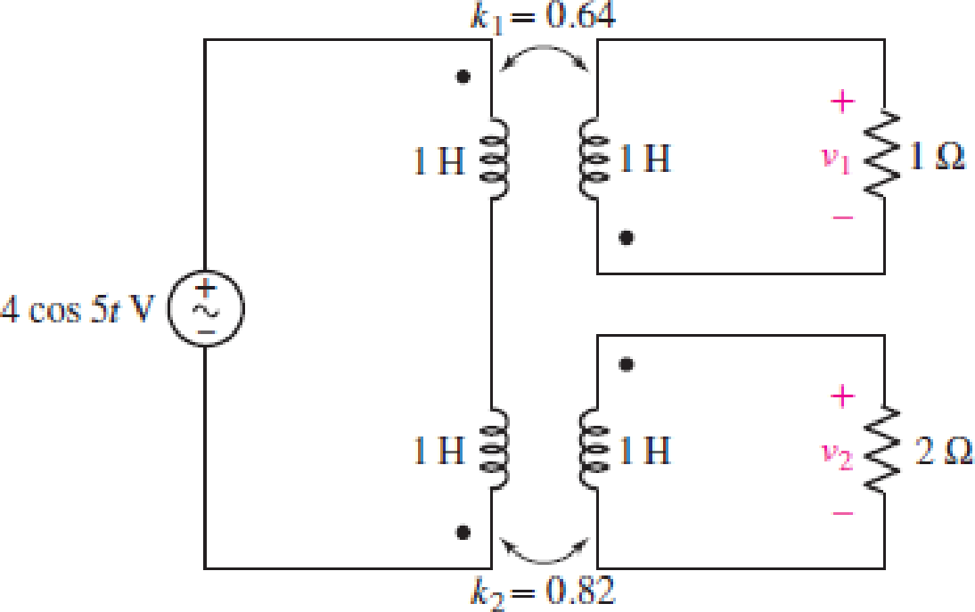
Compute v1, v2, and the average power delivered to each resistor in the circuit of Fig. 13.54.
FIGURE 13.54
Expert Solution & Answer
Want to see the full answer?
Check out a sample textbook solution
Students have asked these similar questions
The networks in Fig. 13.65 are equivalent. Calculate the values of L1, L2, and M.
4,4
I (us)
-40°
FIG. 13.90
Determine the phasor currents I, and I₂ in the circuit of Fig. 13.13.
5Ω
j2 Ω
100 /60° V
4₁
j6 Ω
I
+ -j4Ω
j3 Ω
Chapter 13 Solutions
ENGINEERING CIRCUIT...(LL)>CUSTOM PKG.<
Ch. 13.1 - Assuming M = 10 H, coil L2 is open-circuited, and...Ch. 13.1 - For the circuit of Fig. 13.9, write appropriate...Ch. 13.1 - For the circuit of Fig. 13.11, write an...Ch. 13.2 - Let is = 2 cos 10t A in the circuit of Fig. 13.14,...Ch. 13.3 - Element values for a certain linear transformer...Ch. 13.3 - (a) If the two networks shown in Fig. 13.20 are...Ch. 13.3 - If the networks in Fig. 13.23 are equivalent,...Ch. 13.4 - Prob. 8PCh. 13.4 - Let N1 = 1000 turns and N2 = 5000 turns in the...Ch. 13 - Prob. 1E
Ch. 13 - With respect to Fig. 13.36, assume L1 = 500 mH, L2...Ch. 13 - The circuit in Fig. 13.36 has a sinusoidal input...Ch. 13 - Prob. 4ECh. 13 - Prob. 5ECh. 13 - The circuit in Fig. 13.38 has a sinusoidal input...Ch. 13 - The physical construction of three pairs of...Ch. 13 - Prob. 8ECh. 13 - Prob. 9ECh. 13 - Calculate v1 and v2 if i1 = 5 sin 40t mA and i2 =...Ch. 13 - Prob. 11ECh. 13 - For the circuit of Fig. 13.41, calculate I1, I2,...Ch. 13 - Prob. 13ECh. 13 - Prob. 14ECh. 13 - In the circuit of Fig. 13.43, M is reduced by an...Ch. 13 - Prob. 16ECh. 13 - Prob. 17ECh. 13 - Prob. 18ECh. 13 - Prob. 19ECh. 13 - Note that there is no mutual coupling between the...Ch. 13 - Prob. 21ECh. 13 - (a) Find Zin(j) for the network of Fig 13.50. (b)...Ch. 13 - For the coupled coils of Fig. 13.51, L1 = L2 = 10...Ch. 13 - Prob. 24ECh. 13 - Prob. 25ECh. 13 - Prob. 26ECh. 13 - Consider the circuit represented in Fig. 13.53....Ch. 13 - Compute v1, v2, and the average power delivered to...Ch. 13 - Assume the following values for the circuit...Ch. 13 - Prob. 30ECh. 13 - Prob. 31ECh. 13 - Prob. 32ECh. 13 - Prob. 33ECh. 13 - Prob. 34ECh. 13 - Prob. 35ECh. 13 - Prob. 36ECh. 13 - Prob. 37ECh. 13 - FIGURE 13.60 For the circuit of Fig. 13.60, redraw...Ch. 13 - Prob. 39ECh. 13 - Prob. 40ECh. 13 - Calculate the average power delivered to the 400 m...Ch. 13 - Prob. 42ECh. 13 - Calculate the average power delivered to each...Ch. 13 - Prob. 44ECh. 13 - Prob. 45ECh. 13 - Prob. 46ECh. 13 - Prob. 47ECh. 13 - Prob. 48ECh. 13 - A transformer whose nameplate reads 2300/230 V, 25...Ch. 13 - Prob. 52ECh. 13 - As the lead singer in the local rock band, you...Ch. 13 - Obtain an expression for V2/Vs in the circuit of...Ch. 13 - Prob. 55E
Knowledge Booster


Learn more about
Need a deep-dive on the concept behind this application? Look no further. Learn more about this topic, electrical-engineering and related others by exploring similar questions and additional content below.Similar questions
- 39. Select values for a and h in the circuit of Fig. 13.65 so that the ideal source supplies 1000 W, half of which is delivered to the 100-2 load. 25 N 1:a 1:b 100 N 100 V rms b = 0.8944, a = 5 elll ell ell ellarrow_forward54. Calculate V2 and the average power delivered to the 8 2 resistor of Fig. 13.72 if V, = 10/15° V, and the control parameter c is equal to (a) 0; (b) 1 mS. %3D a:b cV2 8Ω ell ellearrow_forwardHW19 *13.22 Find current I, in the circuit of Fig. 13.91. -j 50 2 I. j20 Ω j40 2 j60 2. j102 j80 23 j30 2 50/0° V 100 2 wwarrow_forward
- Find V, in the circuit of Fig. 13.40. 4Ω W 240/0° V 1:2 elex 892 www + Vo 292 www 80 As an ideal remains the Equation Thus,arrow_forwardRefer to the autotransformer circuit in Fig. 13.44. Calculate: (a) I₁, I₂, and I, if Z₁ = 8 + j6, and (b) the complex power supplied to the load. 1₂ 120/30⁰ Vrms eeeee *+ 120 turns 80 turns V₂ 74₁ Zarrow_forwardTOPIC: Ohm's Law, Power and Generating Direct CurrentDirect Current Circuit AnalysisInductor, Capacitor, Generating Alternating Current Please Answer: V6 R45 R2345arrow_forward
- Determine the voltage V, in the circuit of Fig. 13.10. j1Ω 4 Ω 120 /45° V ( j8Ω3 &j5Ω 12 Figure 13.10 I + 10 Ω Voarrow_forward13.18 Find the Thevenin equivalent to the left of the load H Z in the circuit of Fig. 13.87. ML k = 0.5 j2 Q all -j4 2 j5 N j20 Q 120 0° V Z 4 + j6 Qarrow_forwardIn the d.c. network shown in Fig.13.47, A is the feeding point and Is maintained at 250 V. The resistances of the various branches (go and return) are indicated in the figure. Determine the current in each branch. + 12 A 0.4 a 36 A 0.8 Q + 16 A 0.40 8A D Fig. 1347 Ans:- [AB = 144A ; BC = 2A ; DC = 5A ; AD = 13A] 0.8 a 04 aarrow_forward
- A d.c. 2-wire ring main ABCDEA is fed from 230 V supply as shown in Fig. 13.46. The resistance of each section (go and re- turn) AB, BC, CD, DE and EA is 0-1 W. The loads are tapped off as shown. Find the voltage at each load point. [VB= 227 V ; Vc=225 V ; V, = 225 V ; VE = 226 V] 2.arrow_forwardFind the Norton equivalent for the circuit in Fig. 13.84 at terminals a-b. Figure 13.84 j5 2 j10 2 a 10 2 j10 2 2 A bo ellarrow_forwardFundamentals of Electrical Engineering 2020/2021 Dr. Yaseen H. Tahir We can note that IL and Vi are same in both cases. Example: a) Convert the current source of Figure below to an equivalent voltage source. b) Prove your answer. (Home work) Rs 10KQ 20KO 5 mA b.arrow_forward
arrow_back_ios
SEE MORE QUESTIONS
arrow_forward_ios
Recommended textbooks for you
 Introductory Circuit Analysis (13th Edition)Electrical EngineeringISBN:9780133923605Author:Robert L. BoylestadPublisher:PEARSON
 Delmar's Standard Textbook Of ElectricityElectrical EngineeringISBN:9781337900348Author:Stephen L. HermanPublisher:Cengage Learning
 Programmable Logic ControllersElectrical EngineeringISBN:9780073373843Author:Frank D. PetruzellaPublisher:McGraw-Hill Education
 Fundamentals of Electric CircuitsElectrical EngineeringISBN:9780078028229Author:Charles K Alexander, Matthew SadikuPublisher:McGraw-Hill Education
 Electric Circuits. (11th Edition)Electrical EngineeringISBN:9780134746968Author:James W. Nilsson, Susan RiedelPublisher:PEARSON
 Engineering ElectromagneticsElectrical EngineeringISBN:9780078028151Author:Hayt, William H. (william Hart), Jr, BUCK, John A.Publisher:Mcgraw-hill Education,
Introductory Circuit Analysis (13th Edition)
Electrical Engineering
ISBN:9780133923605
Author:Robert L. Boylestad
Publisher:PEARSON
Delmar's Standard Textbook Of Electricity
Electrical Engineering
ISBN:9781337900348
Author:Stephen L. Herman
Publisher:Cengage Learning
Programmable Logic Controllers
Electrical Engineering
ISBN:9780073373843
Author:Frank D. Petruzella
Publisher:McGraw-Hill Education
Fundamentals of Electric Circuits
Electrical Engineering
ISBN:9780078028229
Author:Charles K Alexander, Matthew Sadiku
Publisher:McGraw-Hill Education
Electric Circuits. (11th Edition)
Electrical Engineering
ISBN:9780134746968
Author:James W. Nilsson, Susan Riedel
Publisher:PEARSON
Engineering Electromagnetics
Electrical Engineering
ISBN:9780078028151
Author:Hayt, William H. (william Hart), Jr, BUCK, John A.
Publisher:Mcgraw-hill Education,
Mesh Current Problems in Circuit Analysis - Electrical Circuits Crash Course - Beginners Electronics; Author: Math and Science;https://www.youtube.com/watch?v=DYg8B-ElK0s;License: Standard Youtube License