
Concept explainers
Videos
The maximum and minimum output voltage in the MC14573 circuit such that op-amp remains biased in its linear region.
Answer to Problem 13.10TYU
The input common mode voltage range for the MC14573 op-amp is
Explanation of Solution
Given:
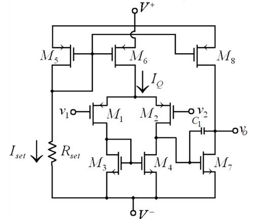
Following is given circuit of the MC14573 op-amp equivalent circuit
Given data,
The transistor parameters are
And the circuit parameters are
The given width to length ratio of
Calculation:
For transistors
Hence,
Now assuming the transistor
currents are given as
We know that the reference current and source to gate voltage is also related by
Now combining equation (1) and (2) yields the source to gate voltage of
Using quadratic equation,
Hence,
Now from equation (1) we have
The reference current is
Similarly, the source to gate voltage of
We know that
Therefore, the source-to-drain saturation voltage is
Now the maximum input voltage is given as
Therefore, the maximum input voltage is
Now for transistor
Therefore,
Now
Where
Now
Therefore, the source-to-gate voltage of
We know that
Therefore, the source-to-drain saturation voltage is
Now the minimum input voltage is given as
Therefore, the minimum input voltage is
The input common mode voltage range for the MC14573 op-amp is
Want to see more full solutions like this?
Chapter 13 Solutions
MICROELECT. CIRCUIT ANALYSIS&DESIGN (LL)


- The junction at a higher temperature in thermocouple is termed as: a) Transducer junction.b) High-temp junctionc) Hot junctiond) Compensation junctione) Thermos junctionarrow_forwardOp amp and diodes are ideal. Derive Vout and sketch the transfer function of Vin vs Vout. Please show complete solution.arrow_forwardProject # 3 (Use a FET op-amp) You’ve been working with an implementation team to build the following components of a system: The system consists of a DC power supply, filters, instrumentation amplifier, one-state system and A/D converter. Build an AC/DC dual power supply circuit that draws a 55Vp-p sinusoidal voltage, to provide a dc output voltage of +10 V. Find the proper data sheet of the IC regulator and specify ranges of output current and voltage. Full analysis of voltages and currents should be included. What modifications would you recommend to draw more current while maintaining same output voltage? Build a 4th order Butterworth LP filters that cover a signal range 10kHz and a gain of 100V/V each. Use C = 0.01µF with proper values of R’s. Record your findings and include plots (magnitude and phase. Calculate the roll-off of the filter. Build an instrumentation amplifier having a differential gain of 50V/V. Choose the right differential input and common input signals to…arrow_forward
- For the given op-amp circuit, determine: (a) iout/iin2, (b) iin2/iin, (c) iin/Is, and (d) iout/Is.arrow_forwardFor the circuit shown below: Find the maximum and minimum Zener current.arrow_forward04 Choose the correct anawer: 1-The maximum peak-to-peak ripple in output curent of step-down converter with RL load epends on (a) Supply voltage (b)Inductunce of load. (e)Chopping frequency. (d)All of the ubove. 2-The formala of output voltage of boost converter in continuous conduction mode in: (a), = DV, (b) =v, (e)- (d)v-(20 - 1), 3-The condition fint operation of buck converter in continuous conduction mode for a given V. LDand T, is (a) The output current is less than boundary current. (b) The output current is more than houndary current. (e) The uutput current is more er les than boundary current. (d)None of above 4-For the converter with supply voltage varied between 12V and 24V, the output voltage is regulated to value of 15V, the suitable DC-DC converter is: (a) Buck converter. (b)Boost comatar. (c) Buck-boost converter. (d)Forwand converter.arrow_forward
- Ex) A standard two-junction thermocouple configuration is being used to measure the temperature in a wind tunnel. The reference junction is held at a constant temperature of 10 °C. We have only a thermocouple table referenced to 0 °C. Determine the output voltage when the measuring junction is exposed to an air temperature of 100 °C.arrow_forwardAnalyze each of the ideal-op-amp circuits shown in FigureP13.23 to find expressions for io. What is the value of the output impedance for each of these circuits? Why? [Note: The bottom end of the input voltage source is not grounded in part (b) of the figure. Thus, we say that this source is floating.]arrow_forward1) For a series regulator show that the output voltage can be made to be dependent only on a reference voltage and the feedback ratio. 2) list the 5 planar processes for Ic fabrication and explain them. 3) A circuit is built around a bi-polar NPN transistor. The base network has a diode and a capacitor in series while the collector is connected to the power supply through a resistor. if the resistor is connected to ground; i) draw the circuit ii) provide all the masking layout of the circuit 4) Explain the significance of the buried layer in npn transistor fabrication. 5) Draw the lateral view of the layout of a lateral pnp transistor. Label all the diffusion regions. 6) state five differences between series regulators and switching regulators.arrow_forward
- 1- Mention any two advantages of Integrated Circuit . 2- For the circuit given below : Vin is a sine wave Vinpp=6 V and Vref=-2.4 V , Assume Vsat=±12V Name the circuit and draw the input and output waveforms . Vin Vref 3- Explain why open-loop op-amp configurations are not used in linear applications? Draw the block diagram of opamp and define the function of each blockarrow_forward4) Consider the clamping circuit below, assume Vref=3 V and Vin=5sin(wt) ..Draw the output voltage waveform. Clearly mark the max and min of the voltage.. Vrefarrow_forwardThe base-biased circuit in the figure is subjected to an increase in junction temperature from 25°C to 75°C. If βdc = 100 at 25°C and 150 at 75°C, Determine the base current Ib in microampere. Show complete solution. (Answer must in 2 decimal places)arrow_forward
 Introductory Circuit Analysis (13th Edition)Electrical EngineeringISBN:9780133923605Author:Robert L. BoylestadPublisher:PEARSON
 Delmar's Standard Textbook Of ElectricityElectrical EngineeringISBN:9781337900348Author:Stephen L. HermanPublisher:Cengage Learning
 Programmable Logic ControllersElectrical EngineeringISBN:9780073373843Author:Frank D. PetruzellaPublisher:McGraw-Hill Education
 Fundamentals of Electric CircuitsElectrical EngineeringISBN:9780078028229Author:Charles K Alexander, Matthew SadikuPublisher:McGraw-Hill Education
 Electric Circuits. (11th Edition)Electrical EngineeringISBN:9780134746968Author:James W. Nilsson, Susan RiedelPublisher:PEARSON
 Engineering ElectromagneticsElectrical EngineeringISBN:9780078028151Author:Hayt, William H. (william Hart), Jr, BUCK, John A.Publisher:Mcgraw-hill Education,