
Videos
An adiabatic 0.2-m3 storage tank that is initially evacuated is connected to a supply line that carries nitrogen at 225 K and 10 MPa. A valve is opened, and nitrogen flows into the tank from the supply line. The valve is closed when the pressure in the tank reaches 10 MPa. Determine the final temperature in the tank (a) treating nitrogen as an ideal gas, and (b) using generalized charts. Compare your results to the actual value of 293 K.
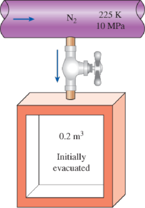
FIGURE P12–101
(a)
The final temperature in the tank by treating nitrogen as an ideal gas and compare the result to the actual value of
Answer to Problem 101RP
The final temperature in the tank by treating nitrogen as an ideal gas is
Explanation of Solution
Write the equation of mass balance.
Here, the inlet mass is
The change in mass of the system for the control volume is expressed as,
Here, the suffixes 1 and 2 indicates the initial and final states of the system.
Consider the given insulated tank as the control volume.
The valve is closed when the pressure in tank reaches to
Rewrite the Equation (I) as follows.
Write the energy balance equation.
Here, the heat transfer is
Since the tank is adiabatic, there is no heat transfer i.e.
The Equation (III) reduced as follows.
Substitute
Express the Equation (V) in molar basis.
Here, the molar mass of nitrogen is
Conclusion:
The inlet condition of the nitrogen is
While considering the nitrogen as the ideal gas, its enthalpy is solely depends on temperature.
Refer Table A-18, “Ideal-gas properties of nitrogen,
The molar enthalpy of nitrogen corresponding to the temperature of
Refer Equation (VI).
The final temperature of the nitrogen is expressed as follows.
Refer Table A-18, “Ideal-gas properties of nitrogen,
The final temperature
Thus, the final temperature in the tank by treating nitrogen as an ideal gas is
The percentage error with the actual temperature value of
The error associated is
(b)
The final temperature in the tank by using generalized departure charts.
Answer to Problem 101RP
The final temperature in the tank by using generalized departure charts is
Explanation of Solution
Refer Table A-1, “Molar mass, gas constant, and critical-point properties”.
The critical temperature and pressure of nitrogen gas is as follows.
The reduced pressure
At inlet:
Refer Figure A-29, “Generalized enthalpy departure chart”.
The enthalpy departure factor
Write formula for enthalpy departure factor
Here, the inlet molar enthalpy at ideal gas state is
Rearrange the Equation (I) to obtain
Write the formula for molar enthalpy at final state
Write the formula for molar internal energy at final state.
Here, the compressibility factor is
The universal gas constant
Conclusion:
Refer part (a) answer for
Substitute
Refer Equation (VI).
It is given that the actual final temperature of nitrogen is
Consider the exit temperature
The reduced pressure
Refer Figure A-29, “Generalized enthalpy departure chart”.
The enthalpy departure factor
Refer Figure A-15, “Nelson–Obert generalized compressibility chart”.
The compressibility factor
Refer Table A-18, “Ideal-gas properties of nitrogen,
The final molar enthalpy of nitrogen
Substitute
Substitute
Express interpolation formula to determine the final temperature
Substitute
Thus, the final temperature in the tank by using generalized departure charts is
The percentage error with the actual temperature value of
The error associated is
Want to see more full solutions like this?
Chapter 12 Solutions
Thermodynamics: An Engineering Approach


- The temperature of R-134a in a tank at a specified state is to be determined using the ideal gas relation, the van der Waals equation, and the refrigerant tables.arrow_forwardA 0.05-m3 rigid tank initially contains refrigerant134a at 0.8 MPa and 100 percent quality. The tank is connected by a valve to a supply line that carries refrigerant-134a at 1.2 MPa and 40°C. Now the valve is opened, and the refrigerant is allowed to enter the tank. The valve is closed when it is observed that the tank contains saturated liquid at 1.2 MPa. Determine the mass of the refrigerant that has entered the tankarrow_forwardA rigid, insulated tank that is initially evacuated is connected through a valve to a supply line that carries helium at 200 kPa and 120°C. Now the valve is opened, and helium is allowed to flow into the tank until the pressure reaches 200 kPa, at which point the valve is closed. Determine the flow work of the helium in the supply line and the final temperature of the helium in the tank.arrow_forward
- A 0.05-m3 rigid tank initially contains refrigerant134a at 0.8 MPa and 100 percent quality. The tank is connected by a valve to a supply line that carries refrigerant-134a at 1.2 MPa and 40°C. Now the valve is opened, and the refrigerant is allowed to enter the tank. The valve is closed when it is observed that the tank contains saturated liquid at 1.2 MPa. Determine the amount of heat transfer.arrow_forward5. The two tanks (Tank A and Tank B) are connected by a valved tube. Initially, the valve is closed. Tank A contains 1 MPa, 1.5 kg of water vapor at 350°C, and tank B contains 3 kg of saturated water with 150 * C and dryness x=0.5. The valve was opened and the water vapor moved and finally the pressure in the two tanks was equal to 300 kPa. Answer the following questions. (1) Calculate the volumes of tank A and tank B, respectively. (2) Calculate the final temperature and dryness (in case of saturation).arrow_forwardLiquid water at 200 kPa and 20 degress celcius is heated in a chamber by mixing it with superheated steam at 200 kPa and 250 degrees celcius. Liquid water enters the mixing chamber at a rate of 4.2 kg/s, and the chamber is estimated to lose heat to the surrounding air at 23 degress celcius at a rate of 1200 kJ/min. If the mixture leaves the mixing chamber at 200 kPa and 85 degrees celcius determine (a) the mass flow rate of the superheated steam, and (b) the rate of entropy generation during the mixing process.arrow_forward
- A constant-pressure R-134a vapor separation unit separates the liquid and vapor portions of a saturated mixture into two separate outlet streams. Determine the flow power needed to pass 6 L/s of R-134a at 320 kPa and 55 percent quality through this unit. What is the mass flow rate, in kg/s, of the two outlet streams?arrow_forwardAt a pressure of 0.8 MPa and a degree of dryness x = 0.65, the refrigerant R-134a is heated to saturated steam at constant pressure. Calculate the work done by the refrigerant during the phase change A) 9,7 kJ/kg B) 9,1 kJ/kg C) 65 kJ/kg D) 19,4 kJ/kg E) 6,9 kJ/kgarrow_forward5. The two tanks (Tank A and Tank B) are connected by a valved tube. Initially, the valve is closed. Tank A contains 1 MPa, 1.5 kg of water vapor at 350°C, and tank B contains 3 kg of saturated water at 150°C and dryness x=0.5. The valve was opened and the water vapor moved and finally the pressure in the two tanks was equal to 300 kPa. Answer the following questions. (1) Calculate the volumes of tank A and tank B, respectively. (2) Calculate the final temperature and dryness (in case of saturation). (3) Find the amount of heat transfer during this process.arrow_forward
- A 0.06-m3 rigid tank initially contains refrigerant- 134a at 0.8 MPa and 100 percent quality. The tank is connected by a valve to a supply line that carries refrigerant- 134a at 1.2 MPa and 36°C. Now the valve is opened, and the refrigerant is allowed to enter the tank. The valve is closed when it is observed that the tank contains saturated liquid at 1.2 MPa. Determine (a) the mass of the refrigerant that has entered the tank and (b) the amount of heat transfer.arrow_forwardA 0.25 m^3 rigid tank contains refrigerant-134a at 0.8 MPa and 100 percent quality. The tank is connected by a valve to a supply line that carries refrigerant-134a at 1.25 MPa and 30 ∘C. The valve is opened and the refrigerant is allowed to enter the tank. The valve is closed when it is observed that the tank contains saturated liquid at 1.25 MPa. Determine the heat transfer and the mass of the refrigerant that has entered the tank.arrow_forwardRefrigerant-134a enters an adiabatic compressor as saturated vapor at 100 kPa at a rate of 0.7 m3 /min and exits at 1-MPa pressure. If the isentropic efficiency of the compressor is 87 percent, determine the power input, in kW.arrow_forward
 Elements Of ElectromagneticsMechanical EngineeringISBN:9780190698614Author:Sadiku, Matthew N. O.Publisher:Oxford University Press
 Mechanics of Materials (10th Edition)Mechanical EngineeringISBN:9780134319650Author:Russell C. HibbelerPublisher:PEARSON
 Thermodynamics: An Engineering ApproachMechanical EngineeringISBN:9781259822674Author:Yunus A. Cengel Dr., Michael A. BolesPublisher:McGraw-Hill Education
 Control Systems EngineeringMechanical EngineeringISBN:9781118170519Author:Norman S. NisePublisher:WILEY
 Mechanics of Materials (MindTap Course List)Mechanical EngineeringISBN:9781337093347Author:Barry J. Goodno, James M. GerePublisher:Cengage Learning
 Engineering Mechanics: StaticsMechanical EngineeringISBN:9781118807330Author:James L. Meriam, L. G. Kraige, J. N. BoltonPublisher:WILEY