
Videos
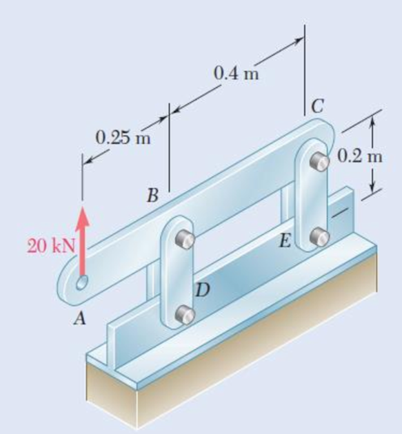
Each of the four vertical links has an 8 × 36-mm uniform rectangular cross section, and each of the four pins has a 16-mm diameter. Determine the maximum value of the average normal stress in the links connecting (a) points B and D, (b) points C and E.
Fig. P1.7
(a)
The maximum value of average normal stress in the links connecting at point B and D.
Answer to Problem 7P
The maximum value of average normal stress in the links connecting at point B and D is
Explanation of Solution
Given information:
The size of rectangular cross section is
The diameter (d) of the each pin is
Calculation:
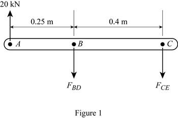
Sketch the free body diagram of link ABC as shown in Figure 1.
Here,
Refer to Figure 1.
Apply the moment equilibrium condition at the point C.
Refer to Figure 1.
Apply the moment equilibrium condition at the point B.
Calculate the net area of one link for tension as follows:
Here, b is the width of the rectangular cross section, h is the depth of the rectangular cross section, and
Substitute
Find the area of network for two parallel links as follows:
Find the average normal stress
Here,
Substitute
Thus, the maximum value of average normal stress in the links connecting at point B and D is
(b)
The maximum value of average normal stress in the links connecting at point C and E.
Answer to Problem 7P
The maximum value of average normal stress in the links connecting at point C and E is
Explanation of Solution
Calculation:
Calculate the net area of one link for tension as follows:
Substitute
Find the area of network for two parallel links as follows:
Find the average normal stress
Here,
Substitute
Thus, the maximum value of average normal stress in the links connecting at point C and E is
Want to see more full solutions like this?
Chapter 1 Solutions
EBK MECHANICS OF MATERIALS
Additional Engineering Textbook Solutions
Engineering Mechanics: Dynamics (14th Edition)
Fundamentals of Aerodynamics
Heating Ventilating and Air Conditioning: Analysis and Design
DeGarmo's Materials and Processes in Manufacturing
Statics and Mechanics of Materials
Automotive Technology: Principles, Diagnosis, and Service (5th Edition)


- .29 Two wooden members of uniform rectangular cross section are joined by the simple glued scarf splice shown. Knowing that P= 11 kN, determine the normal and shearing stresses in the glued splice. 150 mm 15 75 mm Fig. P1.29 and P1.30arrow_forward1.14 Two hydraulic cylinders are used to control the position of the robotic arm ABC. Knowing that the control rods attached at A and D each have a 20-mm diameter and happen to be parallel in the position shown, determine the average normal stress in (a) member AE, (b) member DG. 400 mm E - 300 mm- A Fig. P1.14 F G 150 mm 150 mm 200 mm B D 600 mm- 800 N Carrow_forward5. The load P applied to a steel rod is distributed to a timber support by an annular washer. The diameter of the rod is 22 mm and the inner diameter of the washer is 25 mm, which is slightly larger than the diameter of the hole. Determine the smallest allowable outer diameter d of the washer, knowing that the axial normal stress in the steel rod is 35 MPa and the average bearing stress between the washer and the timber must not exceed 5 MPa. - 22 mmarrow_forward
- Two gage marks are placed exactly 250 mm apart on a 12-mm-diameter aluminum rod with E = 73 GPa and an ultimate strength of 140 MPa. Knowing that the distance between the gage marks is 250.28 mm after a load is applied, determine the stress in the rodarrow_forwardPROBLEM 1.2 Two solid cylindrical rods AB and BC are welded together at B and loaded as shown. Knowing that d = 50 mm and dz = 30 mm, find the average normal stress at the midsection of (a) rod AB, (b) rod BC. 300 mm 40 kN 250 mm V30 KNarrow_forwardEach of the four vertical Ilinks has an 8 x 36-mm uniform rectangular cross section and each of the four pins has a 16-mm diameter. Take P= 19 kN. 0.4 m C 0.25 m 0.2 m B. P Determine the average bearing stress at Bin member ABC, knowing that this member has a 10 x 50-mm uniform rectangular cross section. MPa. The average bearing stress at Bin member ABC is.arrow_forward
- PROBLEM 1.3 3 in. 30 kips Two solid cylindrical rods AB and BC are welded together at B and loaded as shown. Determine the magnitude of the force P for which the tensile stress in rod AB is twice the magnitude of the compressive stress in rod BC. 30 kips 40 in PROBLEM 1.4 In Prob. 1.3, knowing that P = 40 kips, determine the average normal stress at the midsection of (a) rod AB, (b) rod BC.arrow_forward2.13 A steel plate, which is 1.5 m by 1.5 m and 30 mm thick, is lifted by four cables attached to its corners that meet at a point that is 2 m above the plate. Determine the required cross-sectional area of the cables if the stress in them is not to exceed 20 MPa. Steel plate Prob. 2.13 Cablesarrow_forwardTwo wooden members of 80 *120-mm uniform rectangular cross section are joined by the simple glued scarf splice shown. Knowing that β=22° and that the maximum allowable stresses in the joint are, respectively, 400 kPa in tension (perpendicular to the splice) and 600 kPa in shear (parallel to the splice), determine the largest centric load P that can be appliedarrow_forward
- Link BD consists of a single wooden member 38 mm wide and 19.2 mm thick. Knowing that each pin has a 14.3-mm diameter, determine the maximum value of the average normal stress (in MPa) in link BD if θ= 0° and P = 26.7. Round off the final answer to three decimal places.arrow_forwardThree wooden planks are fastened together by a series of bolts to form a column. The diameter of each bolt is 12 mm and the inner diameter of each washer is 16 mm, which is slightly larger than the diameter of the holes in the planks. Determine the smallest allowable outer diameter d of the washers, knowing that the average normal stress in the bolts is 36 MPa and that the bearing stress between the washers and the planks must not exceed 8.5 MPa.arrow_forward1.14 Two hydraulic cylinders are used to control the position of the robotic arm ABC. Knowing that the control rods attached at A and D each have a 20-mm diameter and happen to be parallel in the position shown, determine the average normal stress in (a) member AE, (b) member DG. 400 mm E -300 mm- A F 150 mm 150 mm 200 mm B 600 mm- 800 N Carrow_forward
 Elements Of ElectromagneticsMechanical EngineeringISBN:9780190698614Author:Sadiku, Matthew N. O.Publisher:Oxford University Press
 Mechanics of Materials (10th Edition)Mechanical EngineeringISBN:9780134319650Author:Russell C. HibbelerPublisher:PEARSON
 Thermodynamics: An Engineering ApproachMechanical EngineeringISBN:9781259822674Author:Yunus A. Cengel Dr., Michael A. BolesPublisher:McGraw-Hill Education
 Control Systems EngineeringMechanical EngineeringISBN:9781118170519Author:Norman S. NisePublisher:WILEY
 Mechanics of Materials (MindTap Course List)Mechanical EngineeringISBN:9781337093347Author:Barry J. Goodno, James M. GerePublisher:Cengage Learning
 Engineering Mechanics: StaticsMechanical EngineeringISBN:9781118807330Author:James L. Meriam, L. G. Kraige, J. N. BoltonPublisher:WILEY