
Videos
11.103 and 11 104 Each member of the truss shown is made of steel and has a cross-sectional area of 500 mm2. Using E = 200 GPa, determine the deflection indicated.
11.103 Vertical deflection of joint B.
11.104 Horizontal deflection of joint B.
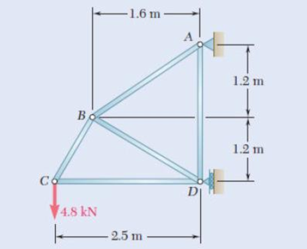
Fig. P11.103 and P11.104
Calculate the horizontal deflection of joint B
Answer to Problem 104P
The horizontal deflection of joint B
Explanation of Solution
Given information:
The Young’s modulus of the steel (E) is
The area of the each member (A) is
The vertical load act at the joint C (P) is
The length of the member AD
The length of the member CD
Calculation:
Consider the horizontal force (Q) at joint B.
Show the free body diagram of the truss members as in Figure 1.
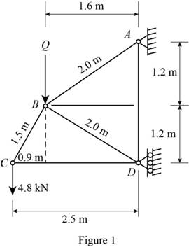
Refer to Figure 1.
Calculate the length of the member AB
The length of the member BD
The length of the member AD
The length of the member CD
Calculate the length of the member BC
Show the diagram of the joint C as in Figure 2.
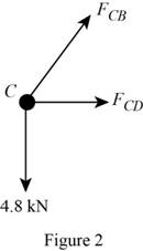
Here,
Refer to Figure 2.
Calculate the horizontal forces by applying the equation of equilibrium:
Sum of horizontal forces is equal to 0.
Calculate the vertical forces by applying the equation of equilibrium:
Sum of vertical forces is equal to 0.
Calculate the force act at the member CD
Substitute
Show the diagram of the joint B as in Figure 3.
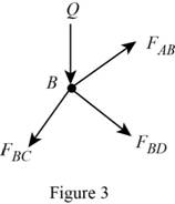
Here,
Refer to Figure 3.
Calculate the horizontal forces by applying the equation of equilibrium:
Sum of horizontal forces is equal to 0.
Calculate the vertical forces by applying the equation of equilibrium:
Sum of vertical forces is equal to 0.
Calculate the force act at the member BD
Substitute
Calculate the force act at the member AB
Substitute
Show the diagram of the joint D as in Figure 4.
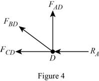
Here,
Refer to Figure 4.
Calculate the vertical forces by applying the equation of equilibrium:
Sum of vertical forces is equal to 0.
Calculate the force act at the member AD
Substitute
Partially differentiate the expression for the force acting at member AB
Calculate the deflection of the member AB
Substitute
Partially differentiate the expression for the force acting at member AD
Calculate the deflection of the member AD
Substitute
Partially differentiate the expression for the force acting at member BD
Calculate the strain energy of the member BD
Substitute
Partially differentiate the expression for force acting at member BC
Calculate the strain energy of the member BC
Substitute
Partially differentiate the expression for force acting at member CD
Calculate the strain energy of the member CD
Substitute
Calculate the vertical deflection of joint B
Substitute
Substitute 0 for Q.
Hence, the horizontal deflection of joint B
Want to see more full solutions like this?
Chapter 11 Solutions
EBK MECHANICS OF MATERIALS


- Question 6* Each member of the truss shown is made of steel and has the cross-sectional area of 400mm². Use Castigliano's theorem to determine the vertical and horizontal deflections of joint A. P = 3 KN E = 200 GPa A VP m F 2.5 kN 1 m. E B -1 m. D 1 marrow_forwardi need answer on this asap. thank you! Each of the links AB and CD is made of aluminum and has a cross-sectional area of 0.2 sq.in. Knowing that they support the rigid member BC, determine the downward deflection (in inches) of point B. if x = 13.7 in, y = 28.1 in, z = 20 in, E = 10754407 psi, and P = 26 kips. Round off the final answer to five decimal places.arrow_forwardEach of the links AB and CD is made of aluminum and has a cross-sectional area of 0.19 sq.in. Knowing that they support the rigid member BC, determine the downward deflection (in inches) of point E. if x = 15.4 in, y = 24.5 in, z = 22 in, E = 10879257 psi, and P = 45 kips. Round off the final answer to five decimal places. ... D E Вarrow_forward
- Each of the links AB and CD is made of aluminum and has a cross-sectional area of 0.11 sq.in. Knowing that they support the rigid member BC, determine the downward deflection (in inches) of point E. if x = 17.5 in, y = 23.7 in, z = 21 in, E = 10863545 psi, and P = 46 kips. Round off the final answer to five decimal places. ... D E yarrow_forward3.2 kN 300 mm B 75 mm A 9.77 The steel bars BE and AD each have a 6 × 18-mm cross section. Knowing that E = 200 GPa, determine the deflections of points A, B, and C of the rigid bar ABC. 400 mm-+400 mm Fig. P9.77arrow_forwardA 7/8-in.-diameter rod BC is attached to the lever AB and to the fixed support at C. Lever AB has a uniform cross section 38 in. thick and 1 in. deep. For the loading shown, determine the deflection of point A. Use E=29 *106 psi and G=11.2 *106 psi.arrow_forward
- 11.22 (B). Determine the vertical deflection of point A on the bent cantilever shown in Fig. 11.29 when loaded at A with a vertical load of 25 N. The cantilever is built in at B, and El may be taken as constant throughout and equal to 450 N m?. [B.P.] [0.98 mm.] B. 125 mm rad. -125mm A 25Narrow_forwardBoth portions of the rod ABC are made of an aluminum for which E = 70.4GPa. Knowing that the magnitude of Q is 31876 N, m = 0.35 m, and n = 0.55 m, determine the value of P (in N) so that the deflection at A is zero.arrow_forwardA compression member of 1.5-m effective length consists of a solid 30-mm-diameter brass rod. In order to reduce the weight of the member by 25%, the solid rod is replaced by a hollow rod of the cross section shown. 15 mm Determine (a) the percent reduction in the critical load, (b) the value of the critical load for the hollow rod. Use E = 200 GPa. 30 mm 30 mmarrow_forward
- Both portions of the rod ABC are made of an aluminum for which E = 69.9GPA. Knowing that the magnitude of Q is 32314 N, m = 0.37 m, and n = 0.54 m, determine the value of P (in N) so that the deflection at A is zero. Express your answer in four decimal places. ... A 20-mm diameter 60-mm diameterarrow_forwardPortion BC of the rod ABC are made of an aluminum for which E= 70 GPa and portion AB is made of steel for which E = 200 GPa. Given: P = 9 kN, a = 0.6 m, b=0.7 m and the diameter of rod AB is c = 36 mm, (a) Determine the value of Q so that the deflection at A is zero (b) The corresponding deflection of point B 60-mm diameterarrow_forwardProblem 1: Determine the horizontal and vertical deflections at B of the truss. 10 ft D 5 ft (4 in.²) (6 in.²) 20 k E 20 ft E 10,000 ksi (6 in.) Problem 2: Determine the smallest cross-sectional area A for the members of the truss shown, so that the vertical deflection at B does not exceed 0.4 inches. 10 k B 2 at 6 ft 12 ft EA= constant E = 1,600 ksi a-6.5 (10 F 10 k H B 45 k F Problem 3: Determine the vertical deflection at G of the truss due to a temperature increase of 65°F in AB, BC, CD, and DE, and a temperature drop of 20°F in FG and GH. 4 at 12 ft 48 t 3 ft 12 ftarrow_forward
 Elements Of ElectromagneticsMechanical EngineeringISBN:9780190698614Author:Sadiku, Matthew N. O.Publisher:Oxford University Press
 Mechanics of Materials (10th Edition)Mechanical EngineeringISBN:9780134319650Author:Russell C. HibbelerPublisher:PEARSON
 Thermodynamics: An Engineering ApproachMechanical EngineeringISBN:9781259822674Author:Yunus A. Cengel Dr., Michael A. BolesPublisher:McGraw-Hill Education
 Control Systems EngineeringMechanical EngineeringISBN:9781118170519Author:Norman S. NisePublisher:WILEY
 Mechanics of Materials (MindTap Course List)Mechanical EngineeringISBN:9781337093347Author:Barry J. Goodno, James M. GerePublisher:Cengage Learning
 Engineering Mechanics: StaticsMechanical EngineeringISBN:9781118807330Author:James L. Meriam, L. G. Kraige, J. N. BoltonPublisher:WILEY