
Videos
A gas refrigeration system using air as the working fluid has a pressure ratio of 5. Air enters the compressor at 0°C. The high-pressure air is cooled to 35°C by rejecting heat to the surroundings. The refrigerant leaves the turbine at −80°C and then it absorbs heat from the refrigerated space before entering the regenerator. The mass flow rate of air is 0.4 kg/s. Assuming isentropic efficiencies of 80 percent for the compressor and 85 percent for the turbine and using constant specific heats at room temperature, determine (a) the effectiveness of the regenerator, (b) the rate of heat removal from the refrigerated space, and (c) the COP of the cycle. Also, determine (d) the refrigeration load and the COP if this system operated on the simple gas refrigeration cycle. Use the same compressor inlet temperature as given, the same turbine inlet temperature as calculated, and the same compressor and turbine efficiencies.
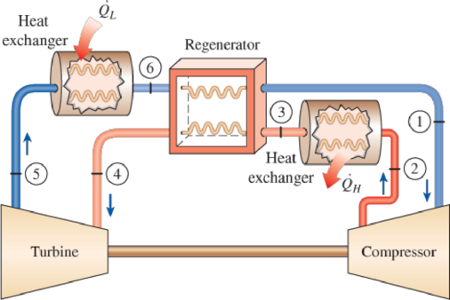
FIGURE P11–79
(a)
The effectiveness of the regenerator.
Answer to Problem 79P
The effectiveness of the regenerator is
Explanation of Solution
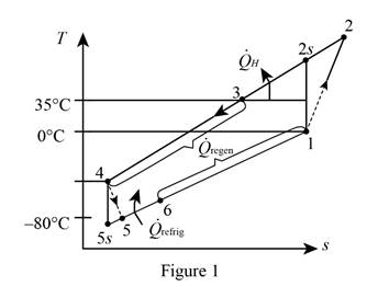
Show the T-s diagram as in Figure (1).
Express the temperature at state 2s.
Here, temperature at state 1 is
Express the temperature at state 2 from the isentropic relations.
Here, isentropic efficiency is
Express temperature at state 5s.
Here, temperature at state 4 is
Express temperature at state 4.
Here, thermal efficiency is
Express the temperature at state 6 using an energy balance.
Here, mass flow rate is
Express the effectiveness of the regenerator.
Here, enthalpy at state 3, 4 and 6 is
Conclusion:
Perform unit conversion of temperature at state 1, 3, and 5 from
Refer Table A-2, “ideal gas specific heats of various common gas”, and write the properties of air.
Substitute
Substitute
Substitute
Substitute
Solve Equations (VII) and (VIII) simultaneously by online calculator to get,
Substitute
Substitute
Hence, the effectiveness of the regenerator is
(b)
The rate of heat removal from the refrigerated space.
Answer to Problem 79P
The rate of heat removal from the refrigerated space is
Explanation of Solution
Express the rate of heat removal from the refrigerated space.
Conclusion:
Substitute
Hence, the rate of heat removal from the refrigerated space is
(c)
The COP of the gas refrigeration cycle.
Answer to Problem 79P
The COP of the gas refrigeration cycle is
Explanation of Solution
Express the net work input of the compressor.
Express the net work output of the turbine.
Express the coefficient of performance of the gas refrigeration cycle.
Conclusion:
Substitute
Substitute
Substitute
Hence, the COP of the gas refrigeration cycle is
(d)
The refrigeration load and the COP of the system.
Answer to Problem 79P
The refrigeration load is
Explanation of Solution
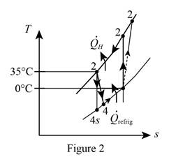
Show the T-s diagram as in Figure (2).
Express temperature at state 4s.
Here, temperature at state 3 is
Express temperature at state 4.
Express the refrigeration load.
Express the net work input.
Express the coefficient of performance of the system.
Conclusion:
Substitute
Substitute
Substitute
Hence, the refrigeration load is
Substitute
Substitute
Hence, the coefficient of performance of the system is
Want to see more full solutions like this?
Chapter 11 Solutions
Thermodynamics: An Engineering Approach


- Condensers in these refrigerators are all_______cooled.arrow_forwardRefrigerant R-134a enters the compressor of a refrigeration machine at 140 kPa pressure and -10°C temperature and exits at 1 MPa pressure. The volumetric flow of the refrigerant entering the compressor is 0.23 m3/minute. The refrigerant enters the throttling valve at 0.95 MPa pressure and 30°C, exiting the evaporator as saturated steam at -18°C. The adiabatic efficiency of the compressor is 78%. Show the cycle in the T-s diagram. a) Calculate the power required to start the compressor. b) Calculate the heat taken in a unit time from the cooled environment. COP=? c) Calculate between the evaporator and the compressor, how much the pressure of the refrigerant drops, and how much is the heat gain.arrow_forwardDescribe the ideal process for an adiabatic nozzle, and define the isentropic efficiency for each device.arrow_forward
- A vapor-compression refrigeration system circulates refrigerant 134a at a rate of 0.15 kg/s. The refrigerant enters the compressor at -10 degrees Celcius and 100 kPa, and exits the compressor at 800 kPa. The isentropic efficiency of the compressor is 76%. Pressure drop through the condenser and evaporator are negligible. The refrigerant exits the condenser at 30 degrees Celcius and 800 kPa. Ignoring the heat transfer between the compressor and its surroundings, determine: The rate at which heat energy is removed from the refrigerated space in kW. The coefficient of perfromance.arrow_forwardA steam turbine cycle running on a Rankin cycle between a condenser pressure of 10 kPa and a boiler pressure of 20 MPa, the steam enters the high pressure turbine at a temperature of 600 ° C. The average turbine expands to 800 kPa and then enters the boiler again to be reheated to 500 ° C. The steam leaves the boiler to a low pressure turbine, where it expands to the condenser pressure. If the expansion and compression in the turbine and the pump is isotropic, and the addition of heat is constant pressure, find the efficiency of the cycle. Note point # 1 at the vapor exit region of the condenserarrow_forwardAn air conditioner using refrigerant-134a as the working fluid is used to keep the temperature of a room at 23°C by giving heat to the external environment at 37°C. The heat gain of the house from the walls and windows is 250 kJ/min; 900 W heat is emitted into the room from the computer, TV and lamps. The refrigerant enters the compressor with a flow rate of 100 L/min in the form of saturated vapor at 400 kPa pressure and leaves the compressor at 70°C at 1200 kPa pressure.a) Draw the cycle by showing the elements of the cycle.b) the actual COP value,c) The highest COP value,d) The smallest refrigerant can have for the same compressor inlet and outlet conditions.Calculate the volumetric flow.arrow_forward
- Steam at 2000 psia and 1000°F enters the high-pressure turbine of a reheat cycle and is expanded adiabatically and reversibly to 200 psia. The steam is then passed through the superheater, from where it exits at the 950°F temperature. The low-pressure turbine expands the steam reversibly and adiabatically to 1 psia. If 7 lbm/s of steam is used and the circulating pump is assumed to operate ideally, the power produced, the added heat rate, and the cycle efficiency are: a) 7049,76 hp ; 12124,5 Btu/s ; 42,2% b) 7400,77 hp ; 11553,7 Btu/s ; 45,1% c) 8350,08 hp ; 13089,6 Btu/s ; 49,8% d) 7944,76 hp ; 11834,2 Btu/s ; 47,6%arrow_forwardConsider a 300 kJ/min refrigeration system that operates on an ideal vapor-compression refrigeration cycle with refrigerant-134a as the working fluid. The refrigerant enters the compressor as saturated vapor at 140 kPa and is compressed to 800 kPa. Show the cycle on a T-s diagram with respect to saturation lines, and determine (a) the quality of the refrigerant at the end of the throttling process, (b) the coefficient of performance, and (c) the power input to the compressor.arrow_forwardDefine the h-s diagram of the actual and isentropic processes of an adiabatic compressor.arrow_forward
- In a steam power plant, the condenser pressure is 10 kPa. The turbine and pump isentropic efficiencies are both 85 %. Draw the schematic and T-S diagrams. Label the points by setting point 1 at the condenser outlet, point 2 at the pump outlet, point 3 at the boiler outlet, and point 4 at the turbine outlet. Use the label 2a and 4a for the points due to the isentropic efficiency of the pump and turbine, respectively. Use 2 decimal places for the enthalpy and other energies in solving and for the final answers. For the steam quality (x) and entropy (s), use 4 decimal places in solving. For the specific volume, use 6 decimal places. The pressure and the temperature of steam that enters the turbine are 4.5 MPa and 800 oC Determine the following: (INPUT YOUR ANSWERS ON THE BLANK SPACES PROVIDED.) Enthalpy at point 1 in kJ/kg = Enthalpy at point 2 in kJ/kg = Enthalpy at point 3 in kJ/kg = Enthalpy at point 4 in kJ/kg = Actual Enthalpy at point 2a in kJ/kg = Actual Enthalpy at point…arrow_forwardIn a steam power plant, the condenser pressure is 10 kPa. The turbine and pump isentropic efficiencies are both 85 %. Draw the schematic and T-S diagrams. Label the points by setting point 1 at the condenser outlet, point 2 at the pump outlet, point 3 at the boiler outlet, and point 4 at the turbine outlet. Use the label 2a and 4a for the points due to the isentropic efficiency of the pump and turbine, respectively. Use 2 decimal places for the enthalpy and other energies in solving and for the final answers. For the steam quality (x) and entropy (s), use 4 decimal places in solving. For the specific volume, use 6 decimal places. The pressure and the temperature of steam that enters the turbine are 4 MPa and 700 oC (use the given values assigned on your name in the table below) Determine the following: Enthalpy at point 1 in kJ/kg= Enthalpy at point 2 in kJ/kg = Enthalpy at point 3 in kJ/kg = Enthalpy at point 4 in kJ/kg = Actual Enthalpy at point 2a in kJ/kg= Actual Enthalpy at…arrow_forwardConsider a refrigrator that operates on the vapor compression refrigeration cycle with R-134a as the working fluid. The refrigerant enters the compressor as saturated vapor at 70 kPa, and exits at 1200 kPa and 90°C, and leaves the condenser as saturated liquid at 1200 kPa. The coefficient of performance of this refrigrator isarrow_forward
 Refrigeration and Air Conditioning Technology (Mi...Mechanical EngineeringISBN:9781305578296Author:John Tomczyk, Eugene Silberstein, Bill Whitman, Bill JohnsonPublisher:Cengage Learning