
Concept explainers
Videos
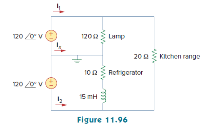
A regular household system of a single-phase three-wire circuit allows the operation of both 120-V and 240-V, 60-Hz appliances. The household circuit is modeled as shown in Fig. 11.96. Calculate:
- (a) the currents I1, I2, and In
- (b) the total complex power supplied
- (c) the overall power factor of the circuit
(a)
Find the currents
Explanation of Solution
Given data:
Refer to Figure 11.96 in the textbook.
The frequency
The circuits performs at both the voltages
The inductance L is
Formula used:
Write the expression for reactance of an inductor
Here,
L is the inductance.
Calculation:
Refer to Figure 11.96 in the textbook.
Substitute
The modified Figure is shown in Figure 1.
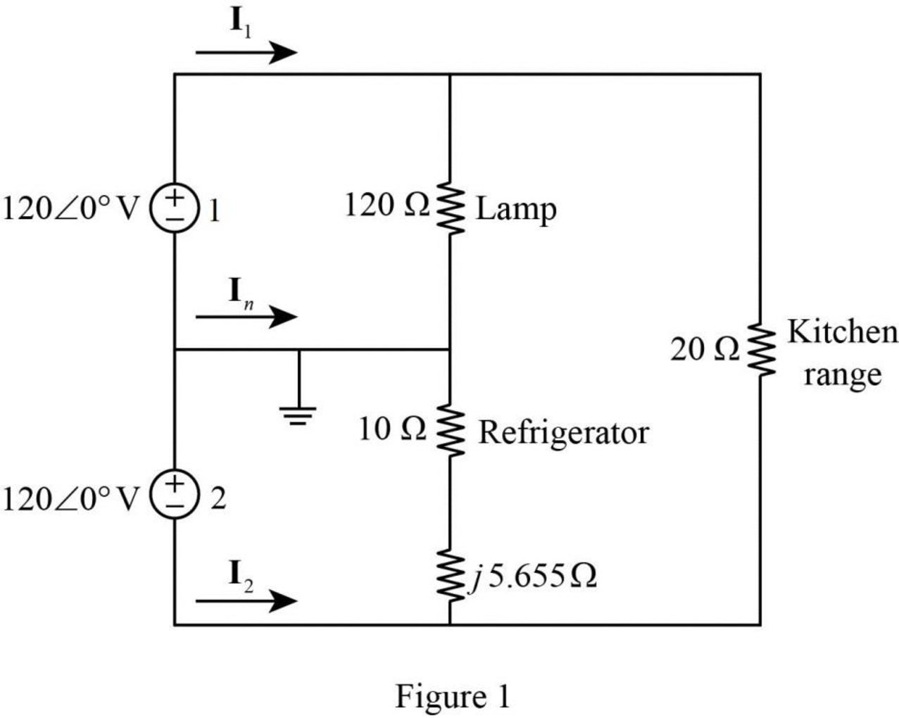
In Figure 1, the current flowing through the lamp
The current flowing through the refrigerator is calculated by using Ohm’s law as follows.
Convert the equation from polar to rectangular form.
The current flowing through the kitchen range
In Figure, apply Kirchhoff’s current law in the circuit. Therefore, the current
Similarly, the current
Convert the equation from rectangular to polar form.
Similarly, the current
Convert the equation from rectangular to polar form.
Conclusion:
Thus, the currents
(b)
Find the total complex power in the circuit of Figure 11.96.
Answer to Problem 85P
The total complex power is
Explanation of Solution
Given data:
Refer to Figure 11.96 in the textbook.
From part (a),
Calculation:
Refer to Figure 1 shown in Part (a).
The complex power delivered by the voltage source 1 is,
Substitute
The complex power delivered by voltage source 2 is,
Substitute
Simply the equation as follows,
Convert the equation from polar to rectangular form.
The total complex power is,
Substitute
Conclusion:
Thus, the total complex power is
(c)
Find the total power factor of the circuit shown in Figure 11.96.
Answer to Problem 85P
The total power factor of the circuit is 0.9888 (lagging).
Explanation of Solution
Given data:
Refer to Figure 11.96 in the textbook.
Formula used:
Write the expression for complex power.
Here,
P is the real power, and
Q is the reactive power.
Write the expression for power factor.
Calculation:
On comparing equation (2) and (3), the real power is,
From equation (2), the apparent power S is,
Substitute
Since,
Conclusion:
Thus, the total power factor of the circuit is 0.9888 (lagging).
Want to see more full solutions like this?
Chapter 11 Solutions
EBK FUNDAMENTALS OF ELECTRIC CIRCUITS


- Q2) A three phase load (motor) draws 30 kW when connected to 440 V rms, 50 Hz line if the power factor is 0.85 lagging, Determine: a) The line current drawn by the motor. b) The KVAR rating of the three capacitors - connected in parallel with the motor that will raise the power factor to 0.95 lagging, and c) The capacitance of each capacitor.arrow_forwardA 3-phase, 50 Hz, 3000 V motor develops 600 H.P. (447·6 kW), the power factor being 0·75 lagging and the efficiency 0·93. A bank of capacitors is connected in delta across the supply terminals and power factor raised to 0·9 lagging. Each of the capacitance units is built of five similar 600-V capacitors. Determine the leading Kvar taken by each three sets.arrow_forwardA 3-phase star-connected alternator is excited to give 6600 V between lines on open circuit. It has a resistance of 0.5 Q and synchronous reactance of 5 2 per phase. Calculate the terminal voltage and regulation at full load current of 130 A when the P.F. is (i) 0.8 lagging, (ii) 0.6 [Rajive Gandhi Technical University, Bhopal, 2000] [(1) 3318 Volts/Ph, + 14.83% (ii) 4265 Volts/Ph, - 10.65%] leading.arrow_forward
- Some parameters are given related to your student ID numbers. These are:V1 = XXX V (first 3 numbers, e.g. 170 V (RMS)) f1 = XXX Hz (assume that your last number is ‘y’, then f1 = (y+1)*10 Hz, e.g. if y=2 then f1=(2+1)*10=30Hz)1) A single-phase load has an active power of P = 2 kW at V1 V @f1Hz and the power factor is cosφ = 0.75. This motor iscompensated to cosφ = 0.85 using a parallel capacitor (the load is modelled as series RL). Determine:a. Reactive power and apparent power before compensation using power factorb. Current before compensationc. R, XL and L values of the loadd. Reactive power and apparent power after compensatione. Find the reactive power difference between compensated and uncompensated status (which will give thecapacitor power) and calculate XC and C using the power difference valuef. Simulate the uncompensated and compensated circuits. Plot voltage and current on components andcalculate the phase shift of the signals from Ving. Plot Vin and Iin comparison for…arrow_forwardConsider the following power system model with the following entities:i. A generator generates a sinusoidal waveform with amplitude of 300 V and angular frequency of 5 radians,ii. The transmission line has a resistance of 1Ω, andiii. A capacitive load with a value of 2F presents at the end of the system. Answer the following questions:(a) Draw the relevant diagram and label all entity values of the power system as described above.(b) Replacing the real source in Figure from part (a) with a complex source, find the response of the steady-state capacitor voltage in time-domain.(c) Repeat the sub-question (a) above, now showing calculations in frequency-domain.(d) Repeat the sub-question (a) above, now showing calculations in s-domain.arrow_forward1. Voltage between 1 kV and 50 kV is defined as: A.Very High Voltage B.Medium Voltage C.Low Voltage D.High Voltage A factory consumes 400, 000 kVAh in a year witth the yearly average power factor 0.75. Calculate the average demand and percentage of annual load factor if the maximum demand is 120kW. A.Average demand = 44.25kW, Load factor = 29% B.Average demand = 44.25kW, Load factor = 39% C.Average demand = 34.25kW, Load factor = 29% D.Average demand = 34.25kW, Load factor = 39% The example of low voltage system is: A.Three-phase, 4-wire, 415 V, up to 45 kVA maximum demand B.Three-phase, 3-wire, 66 kV, 132 kV and 275 kV for exceptionally large load of 25 MVA maximum demand C.Three-phase, 3-wire, 11 kV for load of 1000 kVA maximum demand and above D.Three-phase, 3-wire, 22 kV or 33 kV for load of 5000 kVA maximum demand and above A load rises from zero to 20 kW instantaneosly and stays constant for 2 minutes, then rises about 40…arrow_forward
- Consider the following power system model with the following entities:i. A generator generates a sinusoidal waveform with amplitude of 300 V and angular frequency of 5 radians,ii. The transmission line has a resistance of 1Ω, andiii. A capacitive load with a value of 2F presents at the end of the system. Answer the following questions:(a) Draw the relevant diagram and label all entity values of the power system as described above.(b) Replacing the real source in Figure from part (a) with a complex source, find the response of the steady-state capacitor voltage in time-domain.(d) Repeat the sub-question (a) above, now showing calculations in s-domain.arrow_forward(c) A 240 V rms 50 Hz supply serves four resistive loads that is 10 kW each, an inductive load of 75 kVAR and a 45 kVAR capacitive load. Calculate : (i) The current drawn from the supply. (ii) The KVAR rating and capacitance required to improve the power factor to 0.95 lagging. (iii) The current drawn from the supply after power factor correction.arrow_forward1. A resistor of 50 ohms, a 200mH inductor, and a 1.5 x 10⁻⁴ F capacitor are connected in parallel to a 120-volt, 60 cps source. Calculate: a) the equivalent impedance; b) the current in each load; c) total current; d) the total real, reactive, and apparent powers; e) power factor.arrow_forward
- For the circuit of Fig.11.78 composed of standard values: A. Determine the time constant. B. Write the mathematical expression for the current It after the switch is closed C. Repeat part (b) for VL and VR D. Determine il and VL at one three- and five-time constants. E. Sketch the waveforms of iL,VL and VR.arrow_forwardA 1500 kvA, 3Φ star-connected alternator, 50 Hz,2300 V alternator has a resistance between each pair of terminals as measured by direct currents is 0.16 ohm. Assume that the effective resistance is 1.5 times the ohmic value. A field current of 70 A produces a short-circuit current equal to full load current of 376 A in each line. The same field current produces an emf of 700 V on open circuit. Determine the synchronous reactance of the machine and its full load voltage regulation at 0.8 power factor lagging. [Ans. VR = 22.8 %]arrow_forwardA factory is supplied by a single-phase network of 220V-50Hz and contains in parallel: • 4 motors, each of useful power 5 kW, an efficiency of 0.9 and a power factor of 0.75. • 30 incandescent lamps each of 200W. a) At full load, calculate: 1) The total active power. 2) The total reactive power. 3) The total apparent power. 4) The power factor of the factory. 5) The current absorbed by the factory.arrow_forward
 Introductory Circuit Analysis (13th Edition)Electrical EngineeringISBN:9780133923605Author:Robert L. BoylestadPublisher:PEARSON
 Delmar's Standard Textbook Of ElectricityElectrical EngineeringISBN:9781337900348Author:Stephen L. HermanPublisher:Cengage Learning
 Programmable Logic ControllersElectrical EngineeringISBN:9780073373843Author:Frank D. PetruzellaPublisher:McGraw-Hill Education
 Fundamentals of Electric CircuitsElectrical EngineeringISBN:9780078028229Author:Charles K Alexander, Matthew SadikuPublisher:McGraw-Hill Education
 Electric Circuits. (11th Edition)Electrical EngineeringISBN:9780134746968Author:James W. Nilsson, Susan RiedelPublisher:PEARSON
 Engineering ElectromagneticsElectrical EngineeringISBN:9780078028151Author:Hayt, William H. (william Hart), Jr, BUCK, John A.Publisher:Mcgraw-hill Education,