
Concept explainers
Videos
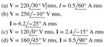
For the following voltage and current phasors, calculate the complex power, apparent power, real power, and reactive power. Specify whether the pf is leading or lagging.
(a)
Find the complex power, apparent power, real power, and reactive power for the given voltage and current phasor. Also mention whether the power factor is leading or lagging.
Answer to Problem 46P
The complex power is
Explanation of Solution
Given data:
The voltage phasor,
The current phasor,
Formula used:
Write the expression to find the complex power
Here,
Write the expression for complex power
Here,
Calculation:
Substitute
Convert equation (5) from polar form to rectangular form. Therefore,
From equation (5), the apparent power
On comparing equation (4) and (6), the real power
From equation (1) and (2), the power factor
Conclusion:
Thus, the complex power is
(b)
Find the complex power, apparent power, real power, and reactive power for the given voltage and current phasor. Also mention whether the power factor is leading or lagging.
Answer to Problem 46P
The complex power is
Explanation of Solution
Given data:
The voltage phasor,
The current phasor,
Calculation:
Substitute
Convert equation (9) from polar form to rectangular form. Therefore,
From equation (9), the apparent power
On comparing equation (4) and (10), the real power
From equation (7) and (8), the power factor
Conclusion:
Thus, the complex power is
(c)
Find the complex power, apparent power, real power, and reactive power for the given voltage and current phasor. Also mention whether the power factor is leading or lagging.
Answer to Problem 46P
The complex power is
Explanation of Solution
Given data:
The voltage phasor,
The current phasor,
Calculation:
Substitute
Convert equation (13) from polar form to rectangular form. Therefore,
From equation (13), the apparent power
On comparing equation (4) and (14), the real power
From equation (11) and (12), the power factor
Conclusion:
Thus, the complex power is
(d)
Find the complex power, apparent power, real power, and reactive power for the given voltage and current phasor. Also mention whether the power factor is leading or lagging.
Answer to Problem 46P
The complex power is
Explanation of Solution
Given data:
The voltage phasor,
The current phasor,
Calculation:
Substitute
Convert equation (17) from polar form to rectangular form. Therefore,
From equation (17), the apparent power
On comparing equation (4) and (18), the real power
From equation (15) and (16), the power factor
Conclusion:
Thus, the complex power is
Want to see more full solutions like this?
Chapter 11 Solutions
EBK FUNDAMENTALS OF ELECTRIC CIRCUITS


- The rms value of v(t)=Vmaxcos(t+) is given by a. Vmax b. Vmax/2 c. 2Vmax d. 2Vmaxarrow_forwardShown in the figure below is an "RL" circuit drive by an AC power source. The AC power source has an RMS voltage of Vps (RMS) = 9.84 Volts and is running at a frequency of f = 8.585e+04 Hz. The resistor has a resistance of R = 2170 and the inductor has an inductance of L = 3.54e-03 Henries. Vps R ww Write the FORMULA for the total impedance of the circuit Ztot = Determine the numerical value of Ztot = 2890.5 Determine the numerical value of $z= = 41 Determine the current through the circuit: • I(PEAK) = 4.81E-3 • I(RMS) = 3.404E-3 Determine the voltage across the resistor: • VR(PEAK) = 7.387 • VR(RMS) = 5.22 ✔✔ Amps ✔Amps Write the FORMULA for the phase of the total impedance of the circuit z... = | tan-1 2701 R x Volts X Volts Determine the voltage across the inductor: • VL(PEAK) = 9.184 • VL(RMS) = 6.49 ✔ Volts Volts L R²+ WL- ✔ degrees 2 If a second circuit were connected in parallel with the inductor, this circuit would be considered as: O a low-pass filter O a capacitive switcher…arrow_forwardShown in the figure below is an "RC" circuit drive by an AC power source. The AC power source has an RMS voltage of Vps (RMS) = 11.58 Volts and is running at a frequency of f = 1.326e+04 Hz. resistor has a resistance of R = 3750 2 and the capacitor has an capacitance of C = 3.17e-09 Farads. Vps R ww Write the FORMULA for the total impedance of the circuit Ztot = Write the FORMULA for the phase of the total impedance of the circuit tot = Determine the numerical value of Ztot = Determine the numerical value of Pztot= Determine the current through the circuit: • I(PEAK) = • I(RMS) = Determine the voltage across the resistor: Amps Amps S2 C degreesarrow_forward
- The source in the circuit shown is a sinusoidal source. The supply voltages across various elements are marked in the figure. The input voltage is: 3V- ww -14 V-10V moon Itarrow_forwardThe 60 Hz AC source and 240 V rms voltage provides a power of 5000 VA for a load with a lagging power factor of 0.85. Determine the reactive power in the capacitor and the value of the capacitor that must be connected in parallel with the load to bring the power factor to 0.92 inductivearrow_forwardP.4: Find the rms value for the following sinusoidal waveforms a. v = 20 sin 754t b. v = 7.07 sin 377t c. i = 0.006 sin(400t + 20°) d. i 16 x 10-3 sin(377t - 10°)arrow_forward
- Q8 The average Power to the Plant Shown m Figure is 2438 kW and Power factor is 0.707 (0gging. The generator is Sinusoidap in waveform with w-377 rad/sec and effective value is 4488 voltos. Determine value of capacitance c Such factor is that power 1 l99ging TC elantarrow_forwardWrite a report to compare between Ac Through capacitance and AC through in inductance then: For the circuit shown beside, find The average power delivered to * .the circuit I 92 100 0 v 82 -j72 b wwarrow_forwardC. Draw a general sine wave V vs t and I vs t plot for a purely resistive and a purely inductive circuit and show leading lagging parameters and clearly mark the phase difference.arrow_forward
- a- Find the RMS values of the load voltage and the load currentb- Calculate and draw the voltage across the load inductancearrow_forwardDraw the waveform of voltage and current under the following conditions: A current which lags the voltage by 60°. A current which leads the voltage by 60°. A current which is in phase with the voltagearrow_forwardP.3: Find the rms value for the following sinusoidal waveforms a. v= 120 sin(377t + 60°) b. i=6x 10³ sin(2# 1000r) c. u=8 x 10⁻⁶ sin(2# 5000 + 30°) P.4: Find the rms value for the following sinusoidal waveforms a. v= 20 sin 754r b. v= 7.07 sin 377r c. i=0.006 sin(400r + 20°) d. i 16 x 10³ sin(377r - 10%) P.5: Write the sinusoidal expressions for voltages and currents having the following rms values at a frequency of 60 Hz with zero phase shifts: a. 4.8 V b. 50 mA c. 2 kVarrow_forward
 Power System Analysis and Design (MindTap Course ...Electrical EngineeringISBN:9781305632134Author:J. Duncan Glover, Thomas Overbye, Mulukutla S. SarmaPublisher:Cengage Learning