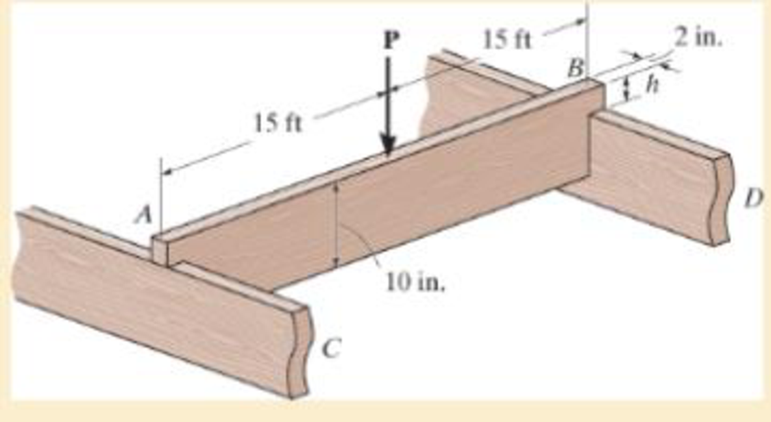
The simply supported joist is used in the construction of a floor for a building. In order to keep the floor low with respect to the sill beams C and D, the ends of the joists are notched as shown. If the allowable shear stress is τallow = 350 psi and the allowable bending stress is σallow = 1500 psi, determine the height h that will cause the beam to reach both allowable stresses at the same time. Also, what load P causes this to happen? Neglect the stress concentration at the notch.

Want to see the full answer?
Check out a sample textbook solution
Chapter 11 Solutions
Mechanics of Materials (10th Edition)
Additional Engineering Textbook Solutions
Thinking Like an Engineer: An Active Learning Approach (4th Edition)
Automotive Technology: Principles, Diagnosis, And Service (6th Edition) (halderman Automotive Series)
Electric Circuits. (11th Edition)
Web Development and Design Foundations with HTML5 (8th Edition)
Vector Mechanics for Engineers: Statics and Dynamics
Thermodynamics: An Engineering Approach
- Consider a single crystal of silver oriented such that a tensile stress is applied along a [112] direction. If slip occurs on a (011) plane and in a [111] direction and is initiated at an applied tensile stress of 15.9 MPa, compute the critical resolved shear stress.arrow_forwardA hypothetical component must not fail when a tensile stress of 15.25 MPa is applied. Determine the maximum allowable internal crack length if the surface energy of the component is 1.50 J/m2. Assume a modulus of elasticity of 350 GPa.arrow_forwardFresh air at 21.1 C in which partial pressure of water vapor is 0.018 atmosphere is blown at the rate of 214 m3/h first through a preheater and then adiabatically saturated in spray chambers to 100% saturation and again reheated this reheated air has humidity of 0.024 kg water vapor per kg dry air. It is assumed that the fresh air and the air leaving the re-heater have the same percentage humidity. Determine:- a- The temperature of preheater, spray-chamber and re-heater b- Heat requirement for preheating and re-heating 11:39 مarrow_forward
- Example(3): 0.15 kg/s steam at atmospheric pressure and superheated to 400 K is bled into an air stream at 320 K and 20 per cent relative humidity. What is the temperature, enthalpy, and relative humidity of the mixed stream if the air is flowing at 5 kg/ s? How much steam would be required to provide an exit temperature of 330 K and what would be the humidity of this mixture? 11:39 مarrow_forwardThe answer to the problem is 31.3rad/s. Please show me how to get the final answerarrow_forwardThe answer to the problem is 1.00 m/s^2. Please show me how to get the final answerarrow_forward
- The answer to the problem is 0.30. Please show me how to get the final answerarrow_forwardThe answer to the problem is 1.96 m/s. Please show me how to get the final answerarrow_forwardA cylindrical tank of diameter D is currently filled with water to a height h, as shown in the figure to the right. Water enters the tank through the pipe at (1) with a cross-sectional area A₁ and a uniform velocity V₁. The height of water in the tank is increasing at a constant rate of 5 mm/s. Given the parameters below, find the volumetric flow rate in the pipe at (2), V2, in cm³/s, and classify it as an inflow or outflow. D = 20 cm h = 0.5 m A₁ = 1 cm² V₁ = 0.1 m/s h 1 V₁ D Pwater = 1,000 kg/m³ V2 2arrow_forward
 Mechanics of Materials (MindTap Course List)Mechanical EngineeringISBN:9781337093347Author:Barry J. Goodno, James M. GerePublisher:Cengage Learning
