
Concept explainers
Videos
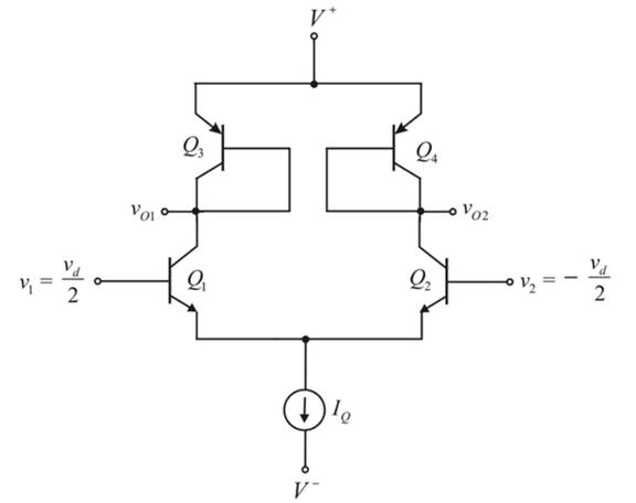
Consider the diff-amp shown in Figure P 11.62 . The circuit parameters are
(a)
To sketch: The small signal equivalent circuit for the differential amplifier.
Answer to Problem 11.62P
The small signal circuit is shown in Figure 2.
Explanation of Solution
Given:
The given circuit is shown below.

Calculation:
The small signal equivalent circuit for the above circuit is shown in Figure 1.
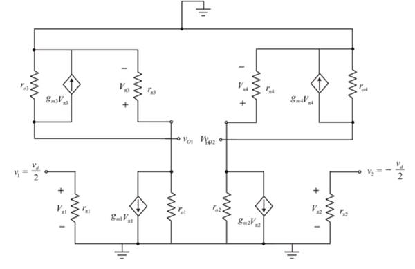
Figure 1
Because of symmetry the value of the currents
The value of the currents
The value of the currents
The value of the currents
For differential up circuit emitter current
Modify the circuit, the required diagram is shown in Figure 2
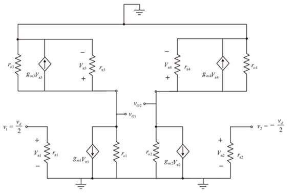
Figure 2
Conclusion:
Therefore, the small signal circuit is shown in Figure 3
(b)
The value of one sided differential voltage gain.
Answer to Problem 11.62P
The value of the differential mode voltage gain is
Explanation of Solution
Given:
The given circuit is shown below.
 Calculation:
Consider the left portion of the circuit as,
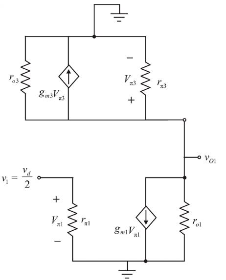
Figure 3
Modify the circuit as shown in Figure 4
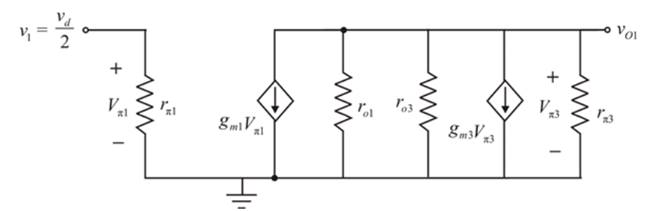
Figure 4
The expression for the output voltage of the above circuit is given by,
The emitter current of the transistor is calculated as,
The expression for the collector current of the transistor
Substitute
Apply KCL at the output node
Substitute
The transconductance of transistor
The transconductance of transistor
The small signal output resistance of
The small signal output resistance of
The small signal resistance
The value of the voltage
Conclusion:
Therefore, the value of the differential mode voltage gain is
(c)
The differential voltage gain of both the sides.
Answer to Problem 11.62P
The value of differential voltage gain is
Explanation of Solution
Given:
The given circuit is shown below.

Calculation:
The expression for the output voltage of the above circuit is given by,
The value of the voltage
Conclusion:
Therefore, the value of differential voltage gain is
(d)
The value of the differential voltage gain of both the sides.
Answer to Problem 11.62P
The value of differential voltage gain is
Explanation of Solution
Given:
The given circuit is shown below.

Calculation:
The expression to determine the value of the two sided differential voltage gain is given by,
Conclusion:
Therefore, the value of differential voltage gain is
Want to see more full solutions like this?
Chapter 11 Solutions
MICROELECT. CIRCUIT ANALYSIS&DESIGN (LL)


- A. Detemine the value of the collector resistor in an npn transistor amplifier with Bpc = 250, VBB = 2.5 V, Vcc = 9 V, VCE = 4 V, and Rg = 100 k2. B. Detemine Ic(sat) for the transistor in below Figure. What is the value of Is necessary to produce saturation? What minimum value of VIN is necessary for saturation? Assume VCE(sat) = 0 V. %3D +5 V 10 kN Rg VINO BDC = 150 1.0 MNarrow_forwardThe DC Current Gain of a Transistor is Select one: a. Ratio of Collector Current to Base Current b. Ratio of Base Current to Collector Current c. Ratio of Emitter Current to Collector Current d. Ratio of Base Current to Emitter Currentarrow_forwardQ1. (a) Consider the amplifier circuit in Figure Q1(a). Given the following: RI = 100 k2 R2 = 56 kN Rc =2 k2 Vcc = +8 V Assume the transistor has B = 100 and VBE(on) = 0.7 V. You may neglect Early effect and use VT = 26 mV. (i) Draw the DC equivalent circuit, then determine Iç and VCE. Draw the AC equivalent circuit using re model. Based on this, determine the parameters Av, Rin and Rout. (ii) Vcc Rc R1 R2 C3 Vout C2 Ci Vin Figure Q1(a)arrow_forward
- A Bipolar junction Transistor with curreat amplification factor being 100, Input Base current is 50μA. Collector voltage is 10 V and biasing voltage being +20 V. Find followings a. Collector current b. Resistance (R1) c. Collector voltage , Emitter voltage , Base Voltage & Collector-Emitter Voltage.arrow_forward(a). If the current gain is 100 and the collector current is 10 mA, the base current is?arrow_forward1. For the circuit in Figure 1: a) Calculate the input and output power if the input signal results in a base current of 6 mA. b) Calculate the input power dissipated by the circuit if Re is changed to 2kn. c) What maximum output power can be delivered by the circuit if Rg is changed to 2 ko? d) If the circuit is biased at its center voltage and center collector operating point, what is the input power for a maximum output power of 2W? 20V Re = 16 2 1.2 ks2 B- 40 100 µF Figure 1arrow_forward
- Figure 1(a) shows a series fed class A amplifier circuit. In order to achieve the maximum efficiency, the Q point must be located at the center of the DC load line as shown in Figure 1(b). This generates the maximum output current swing of Icmax (p – p) RC and the maximum output voltage swing is VCEmax(p – p) = Vcc Assume that the maximum input de power is (1 Vcc Pimax(dc) = Vcc!cQ(max)=Vcc \2° Rc. 2Rc Find the maximum efficiency, 7 of this circuit.arrow_forwardDetermine the DC bias values using DC equivalent circuits (in order of VE, VB, VC)arrow_forwardThe transistor parameters for the circuit in Figure are B, =B2 = 100, VBE1on) = VBE2ton) = 0.7 V, and %3D VA1 =VA2 =0.Find the small signal voltage gain Av = vo/vs. (Note that V-=0.026 V) Vcc=9 V Rib Q1 Vs 1 ko -Ro 20 V 100 Q -wwarrow_forward
- Why there is a difference between the value of a beta dc and the value of a beta ac in the diagram of output characteristics in transistorarrow_forwardConsider the Wilson current source in Figure 1. Assume the reference current IREF is 0.25mA. The transistor parameters are VBE(ON) = 0.7V, VA= 120V and B= 80. a) Determine the output resistance Ro looking into the collector of transistor Q3 of the Wilson current mirror b) What is the change in Io as the output voltage change by +5 V? IREF R Figure 1 wwarrow_forwardCalculate the output impedance for small-signal equivalent circuit. (R1=10 k ohm, r0, =10 k ohm)arrow_forward
 Introductory Circuit Analysis (13th Edition)Electrical EngineeringISBN:9780133923605Author:Robert L. BoylestadPublisher:PEARSON
 Delmar's Standard Textbook Of ElectricityElectrical EngineeringISBN:9781337900348Author:Stephen L. HermanPublisher:Cengage Learning
 Programmable Logic ControllersElectrical EngineeringISBN:9780073373843Author:Frank D. PetruzellaPublisher:McGraw-Hill Education
 Fundamentals of Electric CircuitsElectrical EngineeringISBN:9780078028229Author:Charles K Alexander, Matthew SadikuPublisher:McGraw-Hill Education
 Electric Circuits. (11th Edition)Electrical EngineeringISBN:9780134746968Author:James W. Nilsson, Susan RiedelPublisher:PEARSON
 Engineering ElectromagneticsElectrical EngineeringISBN:9780078028151Author:Hayt, William H. (william Hart), Jr, BUCK, John A.Publisher:Mcgraw-hill Education,