
Videos
Determine the cause for each set of symptoms. Refer to Figure 10-66.
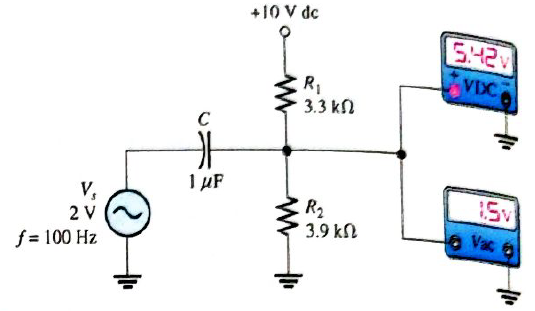
The ac meters indicate the correct readings for this circuit.
Symptom: The dc voltmeter reading is 10 V, and the ac voltmeter reading is
Cause:
Want to see the full answer?
Check out a sample textbook solution
Chapter 10 Solutions
Electronics Fundamentals: Circuits, Devices & Applications


- 9. Sketch the VR waveform for the circuit in Figure 11–56, given the indicated relationship of the input waveforms. FIGURE 11-56 AO G VG- VR Rarrow_forwardFor a positive going pulse, the rising edge is. O a. HIGH to LOW edge O b. falling edge O c. trailing edge O d. leading edgearrow_forwardConvert –5 - j30 to exponential formarrow_forward
- İf the effective voltage value is 80 volts and the effective current value is 4A in the series RLC circuit in the figure, what is the capacitance of the capacitor?arrow_forwardWhen the input signal is AC voltage source reaches zero at every cycle, this will turn the thyristor OFF due to natural behaviour of the source voltage. This is called ONatural commutation O Forced commutation O Forced commutationarrow_forward• If the capacitor and resistive circuit is connected to a DC voltage, what will be the charging time of the capacitor? It will be 1 RC time It will be 10 RC time It will be 3 RC time It will be 5 RC timearrow_forward
- In the following figure find sa Asa turns ratio is A.O-7E A.07001arrow_forwardWhat will be the positive peak voltage (in V) of the circuit using first approximation (answer in 1 decimal place) 15V R -15V 5Varrow_forwardWhat is the voltage between nodes A and B in each circuit in Figure 12–73?arrow_forward
- Identify the temperature range of Nickel wired RTD O a. -80°C to 600° C O b. -80°C to 300° C O c. -80°C to 200° C O d. -100°C to 300° Carrow_forward#8 is draw waveform of circuitarrow_forward5. Determine the output voltage waveform for each circuit in Figures below. o—tet ° o——bt Ji +10vV +ov oV v v, uv% w3 v, Ve nv% 0T v, Ve DVQV 0T v, ~10v =10V -0V @ ® © Ll i Ll o o oI o ol—ptg—o oV v Hov v oy v Y ov% 0K0F Ve Ve nv% K0S vy Ve uv% 0K S v, -10v -0V -1ovarrow_forward
 Introductory Circuit Analysis (13th Edition)Electrical EngineeringISBN:9780133923605Author:Robert L. BoylestadPublisher:PEARSON
 Delmar's Standard Textbook Of ElectricityElectrical EngineeringISBN:9781337900348Author:Stephen L. HermanPublisher:Cengage Learning
 Programmable Logic ControllersElectrical EngineeringISBN:9780073373843Author:Frank D. PetruzellaPublisher:McGraw-Hill Education
 Fundamentals of Electric CircuitsElectrical EngineeringISBN:9780078028229Author:Charles K Alexander, Matthew SadikuPublisher:McGraw-Hill Education
 Electric Circuits. (11th Edition)Electrical EngineeringISBN:9780134746968Author:James W. Nilsson, Susan RiedelPublisher:PEARSON
 Engineering ElectromagneticsElectrical EngineeringISBN:9780078028151Author:Hayt, William H. (william Hart), Jr, BUCK, John A.Publisher:Mcgraw-hill Education,