
Electronics Fundamentals: Circuits, Devices & Applications
8th Edition
ISBN: 9780135072950
Author: Thomas L. Floyd, David Buchla
Publisher: Prentice Hall
expand_more
expand_more
format_list_bulleted
Videos
Textbook Question
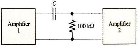
Chapter 10, Problem 42P
What value of coupling capacitor is required in Figure 10-87 so that the signal voltage at the input of amplifier 2 is at least
Disregard the input resistance of the amplifier.
Expert Solution & Answer
Want to see the full answer?
Check out a sample textbook solution
Students have asked these similar questions
Calculate current gain, input and output impedance, and linearity.
Beta = 90
IS = 2E-15
Q/ Why is high frequency (Fsw ) used in Buck Converter circuits
5) With reference to the circuit diagram given below describe in detail the operation of the circuit diagram with all
the applicable waveforms for output voltage, out put current and voltage across the thyristors with alpha=90
degrees
Vs =
Vm sin wr
Vo
(a)
Chapter 10 Solutions
Electronics Fundamentals: Circuits, Devices & Applications
Ch. 10 - In a series RC circuit, the impedance increases...Ch. 10 - In a series RC lag circuit, the output voltage is...Ch. 10 - Admittance is the reciprocal of susceptance.Ch. 10 - In a parallel RC circuit, as frequency is...Ch. 10 - The phase angle of an RC circuit is measured...Ch. 10 - Prob. 6TFQCh. 10 - Prob. 7TFQCh. 10 - The power factor is equal to the tangent of the...Ch. 10 - A purely resistive circuit has a power factor of...Ch. 10 - Prob. 10TFQ
Ch. 10 - Prob. 1STCh. 10 - Prob. 2STCh. 10 - Prob. 3STCh. 10 - When the frequency of the voltage applied to a...Ch. 10 - Prob. 5STCh. 10 - Prob. 6STCh. 10 - The voltages in Problem 6 are measured at a...Ch. 10 - Prob. 8STCh. 10 - Prob. 9STCh. 10 - When the frequency of the source voltage is...Ch. 10 - Prob. 11STCh. 10 - Prob. 12STCh. 10 - Prob. 13STCh. 10 - Prob. 14STCh. 10 - If the bandwidth or a certain low-pass filter is 1...Ch. 10 - Prob. 1TSCCh. 10 - Prob. 2TSCCh. 10 - Prob. 3TSCCh. 10 - Determine the cause for each set of symptoms....Ch. 10 - Determine the cause for each set of symptoms....Ch. 10 - An 8 kHz sinusoidal voltage is applied to a series...Ch. 10 - What is th waveshape of the current in the circuit...Ch. 10 - Find the impedance of each circuit in Figure...Ch. 10 - Determine the impedance and the phase angle in...Ch. 10 - For the circuit of Figure 10-69, determine the...Ch. 10 - Repeat Problem 5 for C=0.0047F.Ch. 10 - Calculate the total current in each circuit of...Ch. 10 - Repeat Problem 7 for the circuits in Figure 10-68.Ch. 10 - For the circuit in Figure 10-70, draw the phase or...Ch. 10 - For the circuit in Figure 10-71, determine the...Ch. 10 - To what value must the rheostat be set in Figure...Ch. 10 - For the lag circuit in Figure 10-73, determine the...Ch. 10 - Repeat Problem 12 for the lead circuit in Figure...Ch. 10 - Determine the impedance for the circuit in Figure...Ch. 10 - Determine the impedance and the phase angle in...Ch. 10 - Repeat Problem 15 for the following frequencies:...Ch. 10 - Determine the impedance and phase angle in Figure...Ch. 10 - For the circuit in Figure 10-78, find all the...Ch. 10 - For the parallel circuit in Figure 10-79, find...Ch. 10 - For the circuit in Figu 10-80, determine the...Ch. 10 - Repeat Problem 20forR=4.7k,C=0.047F,andf=500Hz.Ch. 10 - Convert the circuit in Figure 10-81 to an...Ch. 10 - Determine the voltages across each element in...Ch. 10 - Is the circuit in Figure 10-82 predominantly...Ch. 10 - Find the current through each branch and the total...Ch. 10 - For the circuit in Figure 10-83, determine the...Ch. 10 - In a certain seris RC circuit, the true power is 2...Ch. 10 - In Figure 10-71, what is the true power and the...Ch. 10 - What is the power factor for the circuit of Figure...Ch. 10 - Determine Ptrue, Pr, Pa,andPF for the circuit in...Ch. 10 - The lag circuit in Figure 10-73 also acts as a...Ch. 10 - Plot the frequency response curve for the circuit...Ch. 10 - Draw the voltage phasor diagram for each circuit...Ch. 10 - Thr rms value of the signal voltage out of...Ch. 10 - Determine the cutoff frequency for each circuit in...Ch. 10 - Determine the bandwidth of the circuit in Figure...Ch. 10 - Assume that the capacitor in Figure 10-85 is...Ch. 10 - Each of the capacitors in Figure 10-86 has...Ch. 10 - Determine the output voltage for the circuit in...Ch. 10 - Determine the output voltage for the circuit in...Ch. 10 - A single 240V,60Hz source drives two loads. Load A...Ch. 10 - What value of coupling capacitor is required in...Ch. 10 - Determine the value of R1 required to get a phase...Ch. 10 - Draw the voltage and current phasor diagram for...Ch. 10 - A certain load dissipates 1.5kW of power with an...Ch. 10 - Deteine the series element or element that are in...Ch. 10 - Determine the value of C2 in Figure 10-91 when...Ch. 10 - Draw the schematic for the circuit in Figure 10-92...Ch. 10 - Open file P10-49; files are found at...Ch. 10 - Open file P10-50. Determine if there is a fault...Ch. 10 - www.prenhall.com/floyd. Open file P10-51....Ch. 10 - www.prenhall.com/floyd. Open file P10-52....Ch. 10 - www.prenhall.com/floyd. Open file P10-53....Ch. 10 - www.prenhall.com/floyd. Open file P10-54....
Knowledge Booster


Learn more about
Need a deep-dive on the concept behind this application? Look no further. Learn more about this topic, electrical-engineering and related others by exploring similar questions and additional content below.Similar questions
- 5) With reference to the circuit diagram given below describe in detail the operation of the circuit diagram with all the applicable waveforms for output voltage, out put current and voltage across the thyristors with alpha=90 degrees Vs = Vo V„ sin wr (a)arrow_forwardwhat is the Rin, Rout, gain in given figurearrow_forwardIn a 10C400 CT, the maximum error occurs at what secondary current? O A. The answwer is not given OB.5A O C. 50 A OD. 100 Aarrow_forward
- What is the average value of output voltage, if the ON time of a step up chopper is 0.2 times the total time, and the source voltage of V,? a. 0.2 Vs O b. 0.8 Vs O c. 1.25 Vs d. 2.5 Vsarrow_forwardQ5 just a few of them no need to all. thank youarrow_forwardwhat is the average active power and reactive power of R1?arrow_forward
- A boost converter is operated from a source voltage of 100V with a duty ratio of 0.4. The load resistance is 4000. The internal resistance of inductor is 0.40, then the average output voltage isarrow_forward9. Compute the bias point of the circuit depicted in Figure Vcc=2.5 V 100 ΚΩ Σ1 ΚΩ KQ₁ + 0.5 V- OVCE=738V and IC=1262A OVCE=0.738V and IC=0.001262A OVCE=0.0738V and IC=0.1262A None of the mentioned. OVCE=0.738mV and IC=1262mAarrow_forward92 ۱ ۹:۱ ص Qs= 1107 and Qp= 1041 Qs= 1207 and Qp= 1241 Qs= 1007 and Qp= 1041 Qs= 1107 and Qp= 1141 In the figure shown below we can find output current is equal to.. . if the input voltage is equal to 12 mv 12 kO 12 ka 6 ka No option is correct 10 = 32 uA 10 = 34 uA 10 = 38 uA 10 = 36 uA In the fig. shown below we can find the higher critical frequency due to the inputarrow_forward
- Draw the output waveform for the comparator circuit in figure below. Assume that Q? +Vout(max) = +10 V and Vout(max) = -10V. Vin U1 Vout R1 +3 V 80ko 0- R2 20ko Con'larrow_forwardplease work out the following using the infomation in the attached photo. This is for a Boost converter (a) Output voltage(b) Inductor current ripple (assume it is 20%) (c) Switching frequency (d) Output current (e) Output voltage ripplearrow_forwardConvert the given drain curve into transconductance curve using square law.arrow_forward
arrow_back_ios
SEE MORE QUESTIONS
arrow_forward_ios
Recommended textbooks for you
 Introductory Circuit Analysis (13th Edition)Electrical EngineeringISBN:9780133923605Author:Robert L. BoylestadPublisher:PEARSON
 Delmar's Standard Textbook Of ElectricityElectrical EngineeringISBN:9781337900348Author:Stephen L. HermanPublisher:Cengage Learning
 Programmable Logic ControllersElectrical EngineeringISBN:9780073373843Author:Frank D. PetruzellaPublisher:McGraw-Hill Education
 Fundamentals of Electric CircuitsElectrical EngineeringISBN:9780078028229Author:Charles K Alexander, Matthew SadikuPublisher:McGraw-Hill Education
 Electric Circuits. (11th Edition)Electrical EngineeringISBN:9780134746968Author:James W. Nilsson, Susan RiedelPublisher:PEARSON
 Engineering ElectromagneticsElectrical EngineeringISBN:9780078028151Author:Hayt, William H. (william Hart), Jr, BUCK, John A.Publisher:Mcgraw-hill Education,
Introductory Circuit Analysis (13th Edition)
Electrical Engineering
ISBN:9780133923605
Author:Robert L. Boylestad
Publisher:PEARSON
Delmar's Standard Textbook Of Electricity
Electrical Engineering
ISBN:9781337900348
Author:Stephen L. Herman
Publisher:Cengage Learning
Programmable Logic Controllers
Electrical Engineering
ISBN:9780073373843
Author:Frank D. Petruzella
Publisher:McGraw-Hill Education
Fundamentals of Electric Circuits
Electrical Engineering
ISBN:9780078028229
Author:Charles K Alexander, Matthew Sadiku
Publisher:McGraw-Hill Education
Electric Circuits. (11th Edition)
Electrical Engineering
ISBN:9780134746968
Author:James W. Nilsson, Susan Riedel
Publisher:PEARSON
Engineering Electromagnetics
Electrical Engineering
ISBN:9780078028151
Author:Hayt, William H. (william Hart), Jr, BUCK, John A.
Publisher:Mcgraw-hill Education,
Lead and lag compensation using Bode diagrams; Author: John Rossiter;https://www.youtube.com/watch?v=UBE-Tp173vk;License: Standard Youtube License