
Concept explainers
Videos
The value of the CT secondary current (I’) and VT secondary voltage (V’).
Answer to Problem 10.1P
Explanation of Solution
Given Information:
Calculation:
The secondary voltage of the voltage transformer (V’) is,
Substitute the values in the above equation,
Now, the current (I) entering the primary of the current transformer is,
On substituting the values in the above equation,
And get,
Here, the CT equivalent circuit is,
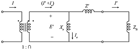
Fig: CT equivalent circuit diagram
Now, the secondary current of CT is,
Substituting the values in the above equation,
From the above equivalent circuit diagram, the secondary current consists of two components, there are
Whereas, I’ is the relay current and Ie is the exciting current.
CT error is Zero in the given question.
So that the exciting current is Zero, (Ie=0), therefore,
Want to see more full solutions like this?
Chapter 10 Solutions
Power System Analysis and Design (MindTap Course List)


- Q/What is the effect of the length of the transmission line on the Phasor measurement unit (PMU) performance ?arrow_forwardWhich Transmission Line Parameter is neglected or ignored in most classifications of Transmission Line Equivalent Circuits? A. The Line Inductance B. The Line Resistance C. The Shunt Conductance D. The Shunt Capacitancearrow_forwardWith the system shown in figures, use 100MVA as system base, and 230 kV as base voltage along the transmission line. 1. Build the Y-bus matrix without the Load. What is the element Y12 in susceptance value? 2. If you are to convert the real power load to a shunt conductance, what is the value of the conductance in per unit?arrow_forward
- A three-phase power of 460 MW is transmitted to a substation located 500 km from the source of power. With VS=1 per unit, VR=0.9 per unit, λ =5000 km, Zc =500 V, and δ=36.878, determine a nominal voltagen level for the lossless transmission line based on Eq. (5.4.29) of the text. Using this result, find the theoretical three-phase maximum power that can be transferred by the lossless transmission line.arrow_forwardA three phase 220KV, 50Hz transmission line supplies a power of 100MW at a power factor of 0.8 lag at the receiving end. The Series resistance, reactance, and shunt susceptance per phase per Km are 0.082, 0.8 2, and 6 x 10⁻⁶mho respectively. Determine the efficiency and regulation for transmission line lengths of 60Km and 200Km (use π)arrow_forwardWhat are the applications for stripline and microstrip transmission lines, and could you provide two examples of characteristic impedance application for each type of transmission line?arrow_forward
- Why the Capacitance effect is neglected in Short Transmission Line. Note please don’t handwringingarrow_forwardExplain how you would create a pcb design for transmission line?arrow_forwardAt the end of the 8 km overhead line given in the figure below, there are two distribution transformers, one of which is 800kVA and the other is 1200kVA, operated with power coefficients of 0.6 and 0.8, respectively. The end-of-line voltage is 6kV. Find the required rated cross section and line head voltage so that the power loss on the line is less than %pk = 10.arrow_forward
- A small manufacturing plant is located 2 km down a transmission line, which has a series reactance of 0.5/km. The line resistance is negligible. The line voltage at the plant is 4800V(rms). and the plant consumes 120kW at 0.85 power factor lagging. Determine the voltage and power factor at the sending end of the transmission line by using (a) a complex power approach and (b) a circuit analysis approach.arrow_forwardWrite down the importance of transmission line constants.arrow_forwardGiven a three-phase load of 125 MW at power factor of 0.8 lagging, operating at 69kV, with a transmission line efficiency of 97% and voltage regulation of 95%, and the line length of 50 km, design a transmission line system and determine the best conductor configuration, conductor resistance and inductance, and conductor radius values to achieve the efficiency and voltage regulation set. Assume a two-bundled conductor configuration with GMR of 0.0496 m and bundle spacing of 30 cm.arrow_forward
 Power System Analysis and Design (MindTap Course ...Electrical EngineeringISBN:9781305632134Author:J. Duncan Glover, Thomas Overbye, Mulukutla S. SarmaPublisher:Cengage Learning