Videos
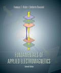
The voltage source of the circuit shown in Fig. P1.29 is given by
Obtain an expression for iL(t), the current flowing through the inductor.
Figure P1.29 Circuit for Problem 1.29.
Want to see the full answer?
Check out a sample textbook solution
Chapter 1 Solutions
Fundamentals of Applied Electromagnetics (7th Edition)
Additional Engineering Textbook Solutions
Electric Circuits (10th Edition)
Programmable Logic Controllers
Electronics Fundamentals: Circuits, Devices & Applications
Electric machinery fundamentals
ELECTRICITY FOR TRADES (LOOSELEAF)
Electric Circuits. (11th Edition)


- 1. A capacitive displacement transducer is connected the circuit shown in Figure 1 below, the output is the current measured by the Ammeter. The capacitance is related to the displacement x by C = A in the SI unit system. The permittivity of free space and the area of one side of one plate A are both constants. Determine the sensitivity at steady state for an excitation at cyclic frequency f. (Hint: you may use the impedance approach.) + E Ammeter A Current / Figure 1 R ww Capacitive C displacement transducerarrow_forwardConsider an inductor whose inductance varies as L(x) = 0.1H/cm. x, where x is the variable length of the inductor. The inductor is connected in series with a 100-W light bulb and a standard power source with the rms output 120 V at 60 Hz. Find the power consumed by the light bulb as a function of the length x in cm. Do not submit the units. The power output, P = At what length of the inductor the power output of the bulb reduces by a factor of 100? The length, x = Watts. Submit Question Units Select an answer Question Help: Message instructor Post to forumarrow_forwardABUSAL For the circuit shown in the following figure, if L= 28 H, V03D13 V, and R= 28 Q, answer the following 2 questions: Tin i(t) Vou(1) L. At what time the inductor is 25% charged from its steady state charging energy. Oa. 0.555 s Ob. 0.866 s Oc. 0.693 s Od. 1.083 s At what time the maximum power is delivered to the inductor.arrow_forward
- A 350 Hz sinusoidal voltage with a maximum amplitude of 120 V at t = 0 is applied across the terminals of an inductor. The maximum amplitude of the steady-state current in the inductor is 20 A. 1.1If the phase angle of the voltage is zero, what is the phase angle in degrees of the current? 1.2What is the inductive reactance in ohm of the inductor? 1.3arrow_forward( NEED ONLY HANDWRITTEN SOLUTION PLEASE OTHERWISE DOWNVOTE).Given a formula for i(t)=10sin(200pit+pi/8) across a capacitor (C=5microfarads). Find the expression of the voltage v(t) across the capcitor. Where Im confused is after integrating the Current and dividing it by C=5microfarads do we need to add +K at the end of the expression?.arrow_forwardRa=0.52 La = 50 mH Va ia Ra W La 4. What is the "order" of this characteristic equation? 5. What is the time constant for this circuit / characteristic equation? 6. What does the time constant represent in physical or "plain speaking" terms? 7. The "root" of this characteristic equation is (circle one answer each for a. and b.) a. Purely Real / Purely Imaginary / Complex b. Stable / Unstable Why?arrow_forward
- %3D 5. In Figure, after switch S is closed at time t 0, the emf of the source is automatically adjusted to maintain a constant current Constant i through S. Current source a) ts)Find the current through the inductor as a function of time. b) At what time is the current through the resistor equal to the current through the inductor? itis di. dis し、arrow_forward10. The sketch (right side) shows a simple RC circuit. The capacitor is initially uncharged, and at t=0 the switch S is closed. Express your answers in terms of Vo, R1, R2 and C. Rz a) Determine the current through each resistor immediately after the switch is closed. b) Determine the charge on the capacitor Q(t) as a function of time after the switch is closed. What are the initial charge Q(t=0), the final charge Q(t -> ∞), and the time constant? Sketch Q(t) vs. t. c) Determine the current through the capacitor I(t) as a function of time after the switch is closed. What are the initial current I(t=0), the final current I(t-> ∞) and the time constant? Sketch I(t) vs. t.arrow_forwardAssume the capacitor (C=10µF) is initially fully discharged. Sketch the Ve(t) and Ic(t) as a function of time as the switch moves from position 1 to 2 to 3 (Assume the capacitor is fully charged before moving to the next switch position). Provide all equations governing the waveforms and their respective time constants. Vc. Ic. R2 =10? C R1 =5? R3 5V, %=20? + 12Varrow_forward
- c) Represent the following signal in Figure Q1(c) in terms of sum of singularity function and sketch its integration. x(t) 1 3 8. Figure Q1(c)arrow_forwardAnswer All questions: Q1: Connect the block diagram shown below. If A-1, trace on the oscilloscope the step function, Vol and Vo2. What is the steady state error? Verify that the function et and i are L.T pairs. Vol Vo2arrow_forwardLe THE NTER VAL Oarrow_forwardarrow_back_iosSEE MORE QUESTIONSarrow_forward_ios
 Introductory Circuit Analysis (13th Edition)Electrical EngineeringISBN:9780133923605Author:Robert L. BoylestadPublisher:PEARSON
 Delmar's Standard Textbook Of ElectricityElectrical EngineeringISBN:9781337900348Author:Stephen L. HermanPublisher:Cengage Learning
 Programmable Logic ControllersElectrical EngineeringISBN:9780073373843Author:Frank D. PetruzellaPublisher:McGraw-Hill Education
 Fundamentals of Electric CircuitsElectrical EngineeringISBN:9780078028229Author:Charles K Alexander, Matthew SadikuPublisher:McGraw-Hill Education
 Electric Circuits. (11th Edition)Electrical EngineeringISBN:9780134746968Author:James W. Nilsson, Susan RiedelPublisher:PEARSON
 Engineering ElectromagneticsElectrical EngineeringISBN:9780078028151Author:Hayt, William H. (william Hart), Jr, BUCK, John A.Publisher:Mcgraw-hill Education,