
EBK ELECTRICAL ENGINEERING
7th Edition
ISBN: 8220106714201
Author: HAMBLEY
Publisher: YUZU
expand_more
expand_more
format_list_bulleted
Concept explainers
Videos
Textbook Question
Chapter 1, Problem 1.5PT
We are given
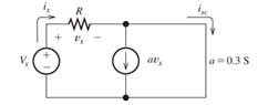
Figure T1.5
Expert Solution & Answer
Want to see the full answer?
Check out a sample textbook solution
Students have asked these similar questions
(a) Use Ohm's Law to derive an expression relating Vout
to Vin using the values of the two resistors. For this
calculation, assume that you have no load attached
(i.e. RL → xx). Make sure to explain in words each
step you take. Hint: Vout is just the voltage drop
across R2. You can draw in a battery with AV = Vin
if that helps you set up the relationships.
R1
Vin
R2
Vout
(O Vin-
Your answer should be in the form, Vout
The term in parentheses is called the gain of the
divider, or the divider ratio.
in·
ww
+
ww
R1 Ω
Rm i
Click here for image
B
M
R2 Ω
Vs V
+
G
ww
R3 2
In the circuit above, R1 = 8.00, R2 = 10.00, R3 = 7.00, Vs = 2.00, and Rm = 6.002. I have ampere units.
Find the voltage at node B with the respect to the reference ground node specified.
Express your answer in volts and round it to two decimal places. Your answer must be purely numerical! Do not type
any letters in the answer box.
1.2Solve the total resistance, total current, individual currents, and individual voltages of the following dc circuits.
EngineeringElectrical EngineeringCircuit Theory
Chapter 1 Solutions
EBK ELECTRICAL ENGINEERING
Ch. 1 - Broadly speaking, what are the two main objectives...Ch. 1 - Prob. 1.2PCh. 1 - List eight subdivisions of electrical engineering.Ch. 1 - Prob. 1.4PCh. 1 - Prob. 1.5PCh. 1 - In the fluid-flow analogy for electrical circuits,...Ch. 1 - The charge of an electron is 1.601019C . A current...Ch. 1 - The ends of a length of wire are labeled a and b....Ch. 1 - The circuit element shown in Figure P1.9 has v=12V...Ch. 1 - Prob. 1.10P
Ch. 1 - The net charge through a cross section of a...Ch. 1 - The current through a particular circuit element...Ch. 1 - The current through a given circuit element is...Ch. 1 - The net charge through a cross section of a...Ch. 1 - A copper wire has a diameter of 2.05 mm and...Ch. 1 - A certain lead acid storage battery has a mass of...Ch. 1 - A circuit element having terminals a and b has...Ch. 1 - An electron moves through a voltage of 9 V from...Ch. 1 - A typical “deep-cycle” battery (used for electric...Ch. 1 - Define the term passive reference configuration....Ch. 1 - Compute the power for each element shown in Figure...Ch. 1 - The terminals of an electrical device are labeled...Ch. 1 - The terminals of a certain battery are labeled a...Ch. 1 - The element shown in Figure P1.24 I has v(t)=10V...Ch. 1 - The current and voltage of an electrical device...Ch. 1 - Suppose that the cost of electrical energy is...Ch. 1 - Figure P1.27 shows an ammeter (AM) and voltmeter...Ch. 1 - Repeat Problem P1.27 with the meters connected as...Ch. 1 - A certain type of D-cell battery that costs $0.50...Ch. 1 - The electronics aboard a certain sailboat consume...Ch. 1 - What s a node in an electrical circuit? Identify...Ch. 1 - State Kirchhoff’s current law.Ch. 1 - Two electrical elements are connected in series....Ch. 1 - Suppose that in the fluid-flow analogy for an...Ch. 1 - Identify elements that are in series in the...Ch. 1 - Consider the circuit shown in Figure P1.36. Which...Ch. 1 - Use KCL to find the values of ia, ic , and id for...Ch. 1 - Find the values of the other currents in Figure...Ch. 1 - Prob. 1.39PCh. 1 - State Kirchhoff’s voltage law.Ch. 1 - Consider the circuit shown in Figure P1.36. Which...Ch. 1 - Use KVL to solve for the voltages va , vb, and vc...Ch. 1 - Solve for the other voltages shown in Figure P1.43...Ch. 1 - Use KVL and KCL to solve for the labeled currents...Ch. 1 - Identify elements that are in parallel in Figure...Ch. 1 - Points a, b, c, and d appear in a certain circuit....Ch. 1 - In your own words, define an ideal conductor; an...Ch. 1 - Name four types of dependent sources and give the...Ch. 1 - State Ohm’s law, including references.Ch. 1 - Draw a circuit that contains a 5 resistance, a...Ch. 1 - Repeat Problem P1.50, placing all three elements...Ch. 1 - The resistance of a certain copper wire is 0.5. ....Ch. 1 - Draw a circuit that contains a 5 resistor, a 10-V...Ch. 1 - Draw a circuit that contains a 5 resistor, a 10-V...Ch. 1 - A power of 100 W is delivered to a certain...Ch. 1 - The voltage across a 10 resistor is given by...Ch. 1 - The voltage across a 10 resistor is given by...Ch. 1 - A certain wire has a resistance of 0.5 . Find the...Ch. 1 - Plot i versus v to scale for each of the parts of...Ch. 1 - Which of the following are self-contradictory...Ch. 1 - Consider the circuit shown in Figure P1.61. Find...Ch. 1 - Consider the circuit shown in Figure P1.62. Find...Ch. 1 - Consider the circuit shown in Figure P1.63. Find...Ch. 1 - Consider the circuit shown in Figure P1.64. Use...Ch. 1 - Determine the value of Ix in the circuit shown in...Ch. 1 - Consider the circuit shown in Figure P1.66. Figure...Ch. 1 - Prob. 1.67PCh. 1 - Consider the circuit shown in Figure P1.68. Figure...Ch. 1 - Solve for the currents shown in Figure P1.69....Ch. 1 - The circuit shown in Figure P1.70 contains a...Ch. 1 - Determine the value of vx and iy in the circuit...Ch. 1 - A 10-V independent voltage source is in series...Ch. 1 - A 10-V independent voltage source is in parallel...Ch. 1 - Consider the circuit shown in Figure P1.74. Figure...Ch. 1 - The circuit shown in Figure P1.75 contains a...Ch. 1 - For the circuit shown in Figure P1.76, solve for...Ch. 1 - For the circuit shown in Figure P1.77, solve for...Ch. 1 - Match each entry in Table T1.1(a) with the best...Ch. 1 - Prob. 1.2PTCh. 1 - The circuit of Figure T1.3 has I1=3A , I2=1A ,...Ch. 1 - The circuit shown in Figure T1.4 has Vs=12V ,...Ch. 1 - We are given Vs=15V , R=10 , and =0.3S for the...Ch. 1 - We are given i4=2A for the circuit of Figure T1.6....
Additional Engineering Textbook Solutions
Find more solutions based on key concepts
Does the severity of an electric shock increase ordecrease with eh of the following changes? a. A decrease in t...
Electric Motors and Control Systems
Write the nodal equations for the network of Fig. 8.137 using the general approach. Find the nodal voltages usi...
Introductory Circuit Analysis (13th Edition)
What is the color code for a 365- five-band precision resistor with a tolerance of 5 percent?
ELECTRICITY FOR TRADES (LOOSELEAF)
Identify the type of input and output configuration for each diff-amp in Figure 18-35.
Electronics Fundamentals: Circuits, Devices & Applications
When travelers from the USA and Canada visit Europe, they encounter a different power distribution system. Wall...
Electric machinery fundamentals
With respect to the circuit in Fig. 5.90, (a) employ Thévenin’s theorem to determine the equivalent network see...
Loose Leaf for Engineering Circuit Analysis Format: Loose-leaf
Knowledge Booster


Learn more about
Need a deep-dive on the concept behind this application? Look no further. Learn more about this topic, electrical-engineering and related others by exploring similar questions and additional content below.Similar questions
- In the figure, ε = 119 V, R₁ = 9.01 Q, R₂ = 29.2 Q, R3 = 38.3 Q, and L = 2.34 H. Immediately after switch S is closed, what are (a) i₁ and (b) i₂? (Let currents in the indicated directions have positive values and currents in the opposite directions have negative values.) A long time later, what are (c) i₁ and (d) i2? The switch is then reopened. Just then, what are (e) i₁ and (f) i₂? A long time later, what are (g) i₁ and (h) i₂? (a) Number (b) Number (c) Number i Units Units Units R₁ R$ Ro L elearrow_forwardReferring to Figure Q1, switch S1 is closed at t= 0 and switch S2 is closed at t= 7s. Find the value of current i (t) at t= 3s. t= 0 10 Ω a S2 Spt= 7 30 V 8Ω 4 H 20 V Figure Q1 O A. 2.7A О В. ЗА о с. 2.5A O D. 2.4A O E. OAarrow_forwardFind the currents I,, I,, and I, in the circuit shown in the figure. (Use Ɛ = 15.00 V.) %3D A circuit containing different branches. of 4.0 N C 6.0 N 10.0 V a d 2.0 N SOLUTION Conceptualize Imagine physically rearranging the circuit while keeping it electrically the same. Can you rearrange it so that it consists of simple series or parallel combinations of resistors? You should find that you cannot. (If the 10.0 V battery were removed and replaced by a wire from b to the 6.0 N resistor, the circuit would consist of only series and parallel combinations.) Categorize We cannot simplify the circuit by the rules associated with combining resistances in series and in parallel. Therefore, this problem is one in which we must use ---Select--- Analyze We arbitrarily choose the directions of the currents as labeled in the figure. According to the label, the current through the 6.0 Q resistor is in which direction in the figure? O to the right O to the left O downward O upward Apply Kirchhoff's…arrow_forward
- Q1) For the following circuit, sketch the output for one cycle of the input voltage. Use a constant-voltage model with VD,=0.7V and. also write an expression for Vo(t). R1 = 10 k2 + R2 = 10 k2 Ą D2 v = 6 sin wt D1 vo + V2 = 4 V V1 = 2 V · +arrow_forwardQ1. Figure-Q1 shows an R-L electrical network. t = 0 R1 L1 i x i2 L2 20 Ω 0.5 H 1.0 H * R3 10 Ω *R2 e(t) = 200 V. Figure-Q1 a. Derive the differential equation for each loop of the circuit in terms of i,, iz and e. b. Derive the expression for i2(t).arrow_forwardConsider the circuit shown in the figure below. (Let R₁ = 6.00 0, R₂ = 8.00 0, and 8 - 10.0 V.) 2.000 W 10.00 www 5.000 www & 16 (a) Find the voltage across R₁. (b) Find the current in R₁. R₂ wwwarrow_forward
- QUESTION 5 What is the steady-state current across R₁ in A given the supply voltage of 8 V is a applied at t=0? Let R1 = 2202, R2 = 350, and C = 0.00017 F. Use scientific notation with 3 significant figures. Omit units. R₁₁ C= R₂arrow_forwardWe are given i 4 = 2 A for the circuit of Figure T1.6. Use Ohm’s law, KCL, and KVL to find the values of i 1, i 2, i 3 and vs.arrow_forwardThe RL network in Figure 1.170 has been at rest for a long period of time with the switch Si open. At time t = 0, Sı is closed as indicated on the schematic. Using the values shown, you are asked to do the following. (a) Calculate values for the inductor current iL(t) at t = 0* and t=∞ (i.e., iL(0*) and İL(0)), and the network time constant t in seconds. (b) Apply these values to generate and write fully the complete time-domain expression for iL(t) found from the solution of the network describing equation. (c) Calculate the value for the rise time t; in seconds. Jg2 S1 t = 0 L 18µH lell 9mA R1 2KΩ İL(t) Eg1 12v R2 6ΚΩ R3 3ΚΩ Figure 1.170 RL network driven by a voltage and current sourcearrow_forward
- Answers are a) w= 0.829 and Ke 7.5 b) G.(s)= (4.263s²+4.5s+1.188)/s Please explain... fastlyarrow_forwardFind vet) for t 2 0 for the circuit of Figure 2. Assume steady-state conditions exist before t = 0. 10 Ω K= 0 1H 10 1/4 FUc 20 V Figure 2arrow_forwardFor the circuit below with switch U1 closing at time t=0 and the initial voltage across Cl equal zero, find the transient response voltage across the resistor R1: (Provide your calculations and reasoning for your answer.) C1 1 U1 20u V1 20Vde R1 100karrow_forward
arrow_back_ios
SEE MORE QUESTIONS
arrow_forward_ios
Recommended textbooks for you
 Introductory Circuit Analysis (13th Edition)Electrical EngineeringISBN:9780133923605Author:Robert L. BoylestadPublisher:PEARSON
 Delmar's Standard Textbook Of ElectricityElectrical EngineeringISBN:9781337900348Author:Stephen L. HermanPublisher:Cengage Learning
 Programmable Logic ControllersElectrical EngineeringISBN:9780073373843Author:Frank D. PetruzellaPublisher:McGraw-Hill Education
 Fundamentals of Electric CircuitsElectrical EngineeringISBN:9780078028229Author:Charles K Alexander, Matthew SadikuPublisher:McGraw-Hill Education
 Electric Circuits. (11th Edition)Electrical EngineeringISBN:9780134746968Author:James W. Nilsson, Susan RiedelPublisher:PEARSON
 Engineering ElectromagneticsElectrical EngineeringISBN:9780078028151Author:Hayt, William H. (william Hart), Jr, BUCK, John A.Publisher:Mcgraw-hill Education,
Introductory Circuit Analysis (13th Edition)
Electrical Engineering
ISBN:9780133923605
Author:Robert L. Boylestad
Publisher:PEARSON
Delmar's Standard Textbook Of Electricity
Electrical Engineering
ISBN:9781337900348
Author:Stephen L. Herman
Publisher:Cengage Learning
Programmable Logic Controllers
Electrical Engineering
ISBN:9780073373843
Author:Frank D. Petruzella
Publisher:McGraw-Hill Education
Fundamentals of Electric Circuits
Electrical Engineering
ISBN:9780078028229
Author:Charles K Alexander, Matthew Sadiku
Publisher:McGraw-Hill Education
Electric Circuits. (11th Edition)
Electrical Engineering
ISBN:9780134746968
Author:James W. Nilsson, Susan Riedel
Publisher:PEARSON
Engineering Electromagnetics
Electrical Engineering
ISBN:9780078028151
Author:Hayt, William H. (william Hart), Jr, BUCK, John A.
Publisher:Mcgraw-hill Education,
Current Divider Rule; Author: Neso Academy;https://www.youtube.com/watch?v=hRU1mKWUehY;License: Standard YouTube License, CC-BY