
Concept explainers
Videos
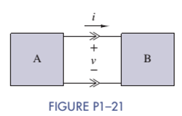
Two electrical devices are connected as shown in Figure P1-21. Using the reference marks shown in the figure, find the power transferred and state whether the power is transferred from A to B or B to A when
(a)
(b)
(c)
(d)
Want to see the full answer?
Check out a sample textbook solution
Chapter 1 Solutions
EBK THE ANALYSIS AND DESIGN OF LINEAR C
Additional Engineering Textbook Solutions
Introductory Circuit Analysis (13th Edition)
Electric Circuits (10th Edition)
Fundamentals of Applied Electromagnetics (7th Edition)
Electric Circuits. (11th Edition)
Basic Engineering Circuit Analysis
Electrical Engineering: Principles & Applications (7th Edition)


- Three 47.1 ohm resistors and three 17.1 H inductors are all in series with a 37 volt battery and a switch. The switch is placed in position A at time t = 0 and switched to position B at time t = 743 ms. Find the voltage across each of the resistors at time t = 1.17 seconds. Owo DO A R R in in ete SW éte لفظوarrow_forwardDetermine the value of the current measured by the ammeter in the Figure. Hint: Write and solve a single mesh equation. Determine the value of the current measured by the ammeter in Amperes.arrow_forwardA series circuit consists of three identical lamps are connected to a battery as shown in Figure below. The switch S, originally open, is closed. What then happens to the brightness of lamp B? A B C S Select one or more: a. It increases b. It does not change c. It decreases d. It drops to zero. + OOOOarrow_forward
- What is the voltage across the 50 Ohm and 5 Ohm resistors? Using the loop hole equation, what is the voltage across the R1? What is R1?arrow_forwardIn the figure &₁ = 3.82 V, &₂ = 1.32 V, R₁ = 5.14 Q, R₂ = 2.69 №, R₂ = 3.61 N, and both batteries are ideal. What is the electric current in (a) R₁, (I₁) (b) R₂, (1₂) and (c) R3, (13)? www R₁ -18₁ www R₂ R$ E₂f-arrow_forwardI did a physics lab and got some values. I want to check them theoretically to see how the results differ. From this diagram, answer the following questions: The laws to be verified included the conservation of current in a node, the addition of potentials for components in series, and the addition of currents for components in parallel. The data : R1: 1094 ohm R2 : 998 ohm R3: 1094 ohmR4: 25 ohm Source 1 : 5 V Source 2 : 1.5 Varrow_forward
- A circuit component carries a current of 2.4 amperes and has a voltage drop of 10 volts across it. What is the resistance R of the component? Round your answer to two significant figures. R = Number S2arrow_forwardThe figure below shows three resistors (R- 13.5 0, R -7.95 0, and Ry- 12.5 0) and two batteries connected in a circuit. 40.0 V R 22.0 V R3 (a) What is the current in each of the resistors? A I2 = A A (b) How much power is delivered to each of the resistors? P1- P2- P3-arrow_forward1. Solve for the voltage across resistor #5 (R5)? 2. Determine the voltage across resistor #3 (R3). 3. How much current is flowing through resistor #2 (R2)?arrow_forward
- What is current i2arrow_forwardA 25mv, 2mA dArsonval movement is to be used in voltmeter whose full scale reading is 100v. The resistance inserted by 100v meter into circuit is Select one: a. 1 x 10⁶ ohm b. None of all c. 1 x 10⁴ ohm d. 1 x 10⁵ ohm e. 1 x 10³ ohmarrow_forwardA current of 5 amperes enters a parallel combination of two unequal, unknown resistors (R1 and R2)supplied from a 45 volts DC source. If the two resistors are connected in series, the current drawnfrom the same source decreases to 937.5 mA. R1 has a lesser resistance than R2. Find R1 and R2.arrow_forward
 Introductory Circuit Analysis (13th Edition)Electrical EngineeringISBN:9780133923605Author:Robert L. BoylestadPublisher:PEARSON
 Delmar's Standard Textbook Of ElectricityElectrical EngineeringISBN:9781337900348Author:Stephen L. HermanPublisher:Cengage Learning
 Programmable Logic ControllersElectrical EngineeringISBN:9780073373843Author:Frank D. PetruzellaPublisher:McGraw-Hill Education
 Fundamentals of Electric CircuitsElectrical EngineeringISBN:9780078028229Author:Charles K Alexander, Matthew SadikuPublisher:McGraw-Hill Education
 Electric Circuits. (11th Edition)Electrical EngineeringISBN:9780134746968Author:James W. Nilsson, Susan RiedelPublisher:PEARSON
 Engineering ElectromagneticsElectrical EngineeringISBN:9780078028151Author:Hayt, William H. (william Hart), Jr, BUCK, John A.Publisher:Mcgraw-hill Education,