Introductory Circuit Analysis (13th Edition)
13th Edition
ISBN: 9780133923605
Author: Robert L. Boylestad
Publisher: PEARSON
expand_more
expand_more
format_list_bulleted
Question
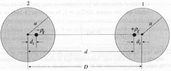
What is the zero potential surface of the 2-wire transmission line in the figure shown?

Transcribed Image Text:ubro
2
og gum so ausdinals of ob-otomcib do ober1
a
di
Pe
as al(\) meqse col
+Pe
di
d
D
Expert Solution
This question has been solved!
Explore an expertly crafted, step-by-step solution for a thorough understanding of key concepts.
Step by stepSolved in 2 steps

Knowledge Booster
Similar questions
- The circle is below(for D1-1N4148 is 1N4148 Diode). and also there have a table(. Note that the first 3 rows of measurement are obtained when the diode is reverse-biased) Vout_dc (V) VD (V) ID (μA) 0.51 -0.51 0.0 0.23 -0.20 0.0 0.10 -0.08 0.0 0.00 0.00 0.0 0.05 0.04 0.0 0.11 0.09 0.0 0.17 0.15 0.1 0.19 0.20 0.1 0.27 0.25 0.4 0.32 0.30 1.6 0.36 0.34 3.1 0.42 0.40 8.2 0.46 0.42 14.3 0.52 0.47 28.0 Questions: 1) plot the diode’s I-V characteristics on a linear scale (ID on the y-axis and VD on the x-axis) 2) [RP4] 3) [RP5]arrow_forwardQ4) Determine and sketch the output voltage across the load resistor (RL) for the circuit shown below (assume Si diodes) V_DC V DC 0,75 (1+ 0.25 V_SIN V SIN RL -1 V SOR V_SQR 0.75 -0.75 V TRI 1 V_TRI -1arrow_forwardFAIRCHILD Discrete POWER & Signal Technologies SEMICONDUCTOR ru 1N4001 - 1N4007 Features • Low torward voltage drop. 10 a14 * High aurge eurrent cepablity. 0.160 4.06) DO 41 COLOR BAND DGNOTEs CAT-Cos 1.0 Ampere General Purpose Rectifiers Absolute Maximum Ratings T-26*Cuness atnerwioe rated Symbol Parameter Value Units Average Recttied Current 1.0 375" lead length a TA - 75°C Tsargei Peak Forward Surge Current 8.3 ms single halr-sine-wave Superimposed on rated load JEDEC method) 30 A Pa Total Device Dissipetion 2.5 20 Derste above 25°C Ra Tag Thermal Resistence, Junction to Amblent 5D Storage Temperature Range 55 to +175 -55 to +150 Operating Junetion Temperature PC "These rarings are imithg valuee above whien the serviceatity or any semiconductor device may te impaired. Electrical Characteristics T-20'Cunieas ofherwise roted Parameter Device Units 4001 4002 4003 4004 4005 4006 4007 Peak Repetitive Reverse Vellage Maximum RME votage DC Reverse Voltage Maximum Reverse Current @ rated VR…arrow_forward
- R1 = 1 kohms R2 = 1.4 kohms R3 = 6.8 kohms E = 8V D1: Si, rB = 2 ohms, rR = 215 kohms D2: Si, rB = 7 ohms, rR = 590 kohms Apply each of the diode approximations and determine: a) Current through D1 b) Voltage across D_2 c) Voltage across R_3arrow_forwardfind the diode voltage and diode current with solution and explanation.arrow_forwardSolve step by steparrow_forward
- b) Use the ALU 74181 in the figure below and the tables (one is enough; second maybe, need to check the new kit) to implement : A + B, A – B, A. B. (MSB) (LSB) 10 (MSB) F3 F2 F1 FO S3 Cn+4 16 s2 20 U14 15 S1 14 so A3 A2 A1 AO B3 B2 B1 B0 M Cn 24 23 22 21 28 27 T26 25 (LSB) (MSB) (LSB)(MSB) (LSB) And given that under M = 1 the circuit performs the following arithmetic and logic functions according to Table 11.1. Input selection S3 Output M-H S2 SI Cn=L. F3 F2 F1 FO A 1 -A В -B A&B AxB 1 A'B 1 Ax(-B) (-A)xB (-A)x(-B) 1 1 ACTIVE HIGH DATA M-L: ARITHMETIC OPERATIONS SELECTION M-H LOGIC s3 s2 s1 so Ino carry) (with carry) F-A PLUS 1 F- LA + B) PLUS 1 F- (A + BI PLUS 1 FUNCTIONS L L F-A F-A+B F-AB F-A H FA+B F-A+T F- MINUS 1 12s COMPL) F-A PLUS AB F- IA + BI PLUS AB L L L L F-0 F-ZERO F- AB F-A PLUS AB PLUS 1 F- (A + BI PLUS AB PLUS 1 L L L H L F-AOB F- AB L L F-A MINUS B MINUS 1 F-A MINUS B F- AB MINUS 1 F- A F-A PLUS AB PLUS1 F-A PLUS B PLUS 1 F- IA + B PLUS AB PLUS 1 L H L F-A PLUS AB…arrow_forwardCan you help me solve this and explain clearly I saw some answers on chegg but I don’t understand it .arrow_forwardCalulate the Condurtwity of pure filiain at when the cCencentratron temperature Cormes is a room 1-6x10" Volt fe ad per Cm3 Take Ue=l1500 cm? per pvolt-Jee at =500 cm tempuature.arrow_forward
- Construct a forward bias diode circuit in multi-sim (desktop, not live). Simulate and find the current through the resistor and the voltage across the resistor.arrow_forwardCan someone explain this problem step by step, pleasearrow_forwardPlease answer in typing format solution please only typing yy Pleasearrow_forward
arrow_back_ios
SEE MORE QUESTIONS
arrow_forward_ios
Recommended textbooks for you
 Introductory Circuit Analysis (13th Edition)Electrical EngineeringISBN:9780133923605Author:Robert L. BoylestadPublisher:PEARSON
 Delmar's Standard Textbook Of ElectricityElectrical EngineeringISBN:9781337900348Author:Stephen L. HermanPublisher:Cengage Learning
 Programmable Logic ControllersElectrical EngineeringISBN:9780073373843Author:Frank D. PetruzellaPublisher:McGraw-Hill Education
 Fundamentals of Electric CircuitsElectrical EngineeringISBN:9780078028229Author:Charles K Alexander, Matthew SadikuPublisher:McGraw-Hill Education
 Electric Circuits. (11th Edition)Electrical EngineeringISBN:9780134746968Author:James W. Nilsson, Susan RiedelPublisher:PEARSON
 Engineering ElectromagneticsElectrical EngineeringISBN:9780078028151Author:Hayt, William H. (william Hart), Jr, BUCK, John A.Publisher:Mcgraw-hill Education,

Introductory Circuit Analysis (13th Edition)
Electrical Engineering
ISBN:9780133923605
Author:Robert L. Boylestad
Publisher:PEARSON

Delmar's Standard Textbook Of Electricity
Electrical Engineering
ISBN:9781337900348
Author:Stephen L. Herman
Publisher:Cengage Learning

Programmable Logic Controllers
Electrical Engineering
ISBN:9780073373843
Author:Frank D. Petruzella
Publisher:McGraw-Hill Education

Fundamentals of Electric Circuits
Electrical Engineering
ISBN:9780078028229
Author:Charles K Alexander, Matthew Sadiku
Publisher:McGraw-Hill Education

Electric Circuits. (11th Edition)
Electrical Engineering
ISBN:9780134746968
Author:James W. Nilsson, Susan Riedel
Publisher:PEARSON

Engineering Electromagnetics
Electrical Engineering
ISBN:9780078028151
Author:Hayt, William H. (william Hart), Jr, BUCK, John A.
Publisher:Mcgraw-hill Education,