Introductory Circuit Analysis (13th Edition)
13th Edition
ISBN: 9780133923605
Author: Robert L. Boylestad
Publisher: PEARSON
expand_more
expand_more
format_list_bulleted
Question
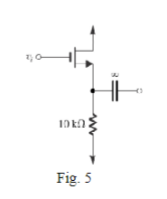
fig5

Transcribed Image Text:The NMOS transistor in the source-follower circuit of Fig. 5 has gm-5mA/V and a large ro. Find the
open-circuit voltage gain and the output resistance.

Transcribed Image Text:10 kn
Fig. 5
Expert Solution
This question has been solved!
Explore an expertly crafted, step-by-step solution for a thorough understanding of key concepts.
Step by stepSolved in 2 steps with 2 images

Knowledge Booster
Similar questions
- please solve, with few steps as possible and show all formulasarrow_forwardThe p-channel MOSFET in the circuit below has V = 1 V and k, = 2 mA/V² (A = 0). + 5 V 9 mA (. vout Q1 10 k VS -5 v a) Is this amplifier a common-source, common-drain, or common-gate configuration? b) Determine the d.c. biasing by calculating VsG and Vsp. c) What is the amplificr's gain A and output resistance Rout?arrow_forwardplease solve, do not use any other resourcesarrow_forward
- b)The transistor consists of three terminals. The main reason for designing configurations is that it requires four terminals in order to provide the input and the output connections of the circuit for effective amplification. Now in your own words describe how Bipolar Transistors Transistor ( BJT ) various configurations are designed with relating diagrams. In your own estimation evalute which one is most widely used when looking at appreciable output for an amplifier?arrow_forwardPlease, I want the solve to the two questions, with a drawing of the equivalent circuit in the case of dc and in the case of small signal.arrow_forward1. Assume that the source voltage for the D-MOSFET in the following figure is measured and found to be 1.6 V. a. Compute lo and Vos- b. If gm = 2000 umho, what is the voltage gain? c. Compute the input resistance of the amplifier. d. Is the D-MOSFET operating in the depletion or the enhancement mode? 100 my pp 1.0 kHz HI C₁ 0.1 µF R₁ 5.1 ΜΩ R₂ 10 ΜΩ +VDD +24 V ① RD 2.7 C3 Rs 330 Ω OV ORI C₂ 33 μFarrow_forward
- B= infinity, Assume BJTs are identical. Find R such that a DC current of 0.25mA for transistors Q1 and 2. Find Rc that results in 3V DC at he collectors of Q1 and 2. Find the differential voltage gain.arrow_forwardAnswer the question correctly with neat handwriting and show some explaination.arrow_forwardI NEED THOSE 5, THE POSSIBLE ANSWERS ARE THOSE WITHIN THE DROPDOWN MENUarrow_forward
- The MOSFET in the circuit below has V = 1 V and kn = 1 mA/V². Determine the values for the drain and source resistors, Rp and Rs., so that the drain current is 2 mA and Vout = 1 V. + 5 V RD Vout RS -5 Varrow_forwardclearly hand write, As soon as possible!arrow_forwardThis is Electronic Devices about BJT. Find the Base Voltage Vb, Emitter Voltage Ve and Collector Voltage Vc using the Thevenin Theorem. draw the Thevenin equivalent circuit.arrow_forward
arrow_back_ios
SEE MORE QUESTIONS
arrow_forward_ios
Recommended textbooks for you
 Introductory Circuit Analysis (13th Edition)Electrical EngineeringISBN:9780133923605Author:Robert L. BoylestadPublisher:PEARSON
 Delmar's Standard Textbook Of ElectricityElectrical EngineeringISBN:9781337900348Author:Stephen L. HermanPublisher:Cengage Learning
 Programmable Logic ControllersElectrical EngineeringISBN:9780073373843Author:Frank D. PetruzellaPublisher:McGraw-Hill Education
 Fundamentals of Electric CircuitsElectrical EngineeringISBN:9780078028229Author:Charles K Alexander, Matthew SadikuPublisher:McGraw-Hill Education
 Electric Circuits. (11th Edition)Electrical EngineeringISBN:9780134746968Author:James W. Nilsson, Susan RiedelPublisher:PEARSON
 Engineering ElectromagneticsElectrical EngineeringISBN:9780078028151Author:Hayt, William H. (william Hart), Jr, BUCK, John A.Publisher:Mcgraw-hill Education,

Introductory Circuit Analysis (13th Edition)
Electrical Engineering
ISBN:9780133923605
Author:Robert L. Boylestad
Publisher:PEARSON

Delmar's Standard Textbook Of Electricity
Electrical Engineering
ISBN:9781337900348
Author:Stephen L. Herman
Publisher:Cengage Learning

Programmable Logic Controllers
Electrical Engineering
ISBN:9780073373843
Author:Frank D. Petruzella
Publisher:McGraw-Hill Education

Fundamentals of Electric Circuits
Electrical Engineering
ISBN:9780078028229
Author:Charles K Alexander, Matthew Sadiku
Publisher:McGraw-Hill Education

Electric Circuits. (11th Edition)
Electrical Engineering
ISBN:9780134746968
Author:James W. Nilsson, Susan Riedel
Publisher:PEARSON

Engineering Electromagnetics
Electrical Engineering
ISBN:9780078028151
Author:Hayt, William H. (william Hart), Jr, BUCK, John A.
Publisher:Mcgraw-hill Education,