
Power System Analysis and Design (MindTap Course List)
6th Edition
ISBN: 9781305632134
Author: J. Duncan Glover, Thomas Overbye, Mulukutla S. Sarma
Publisher: Cengage Learning
expand_more
expand_more
format_list_bulleted
Related questions
Question
Need Handwritten answer Do not use AI

Transcribed Image Text:5. C
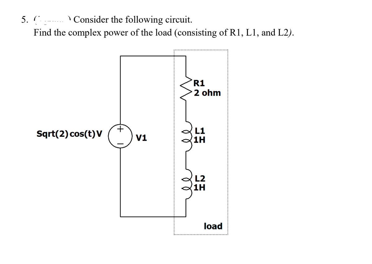
\ Consider the following circuit.
Find the complex power of the load (consisting of R1, L1, and L2).
R1
2 ohm
Sqrt(2) cos(t)V
L1
V1
1H
L2
1H
load
Expert Solution
This question has been solved!
Explore an expertly crafted, step-by-step solution for a thorough understanding of key concepts.

Step by stepSolved in 2 steps with 2 images

Knowledge Booster

Similar questions
- for the given circuit find p & q for the load as shownarrow_forwardA 220V(rms), 50HZ sinusoidal source is connected to the primary side of an ideal transformer with 100 turns on the primary side and 300 turns on the secondary side. Primary line resistance is 22 and inductance is 10mH. Secondary line resistance is 92 and inductance is 100mH. There is a 1002 resistive load connected on the secondary side. Draw a well-labeled circuit diagram and determine: (i) Currents on both sides (ii) Load Voltage (iii) Complex power supplied by the sourcearrow_forwardMinistry of Manpower Directorate General of Technological Education Salalah College of Technology Zlectrical Inginearina Problem - 8 Refer to the circuit below and -25V C2 N. compute the following: i) Total capacitance ii) Voltage across C, iii)Charge across C, iv)Voltage across C5 5 uF C1 5 uF 5 uF C4 5 uF C6 5 uF -16-65V. C5 5 uF (Take V, as 25V) 8-35V VT 25Varrow_forward
- USE STORED VALUES AND ROUND OFF TO FOUR DECIMAL PLACES. PLEASE SHOW COMPLETE SOLUTION.arrow_forwardThe single-phase dual converter below is operated with a 120-V 60HZ supply. The load resistance is 502. The circulating inductance is composed of two 30mH. The delay angles on the Thyristors a1= 45° and a4=135°. Determine the following L1 L2 30mH 30mH V: -- V(p-p): -- V(rms): -- V(dc): -- V(freq): -- D1 D3 D6 D5 V1 R1 120Vrms 60HZ PR1 502 0° D7 D8 D2 D4 a) Calculate the peak circulating current. b) Calculate the Peak current thru Converter 1(D1-D4) and Converter 2(D5-D8) Calculate the Rms voltage of the Output voltage. c)arrow_forwardThe rms value of v(t)=Vmaxcos(t+) is given by a. Vmax b. Vmax/2 c. 2Vmax d. 2Vmaxarrow_forward
- The real power delivered by a source to two impedances, Z1=4+j5 and Z2=10 connected in parallel, is 1000 W. Determine (a) the real power absorbed by each of the impedances and (b) the source current.arrow_forwardPlease Use matrix form in solving this problem. Thank youarrow_forwardPlease answer in typing format please ASAP for the like please Or please ASAP answer in clean handwritingarrow_forward
- NOTE: Polar form for Voltage & Current. Rectangular form for Impedance Find the total impedance of the circuit, total power (apparent) delivered by the current source, Draw the phasor diagram of the voltage and current at the source, the current passing through the R2 and L1 branch, Draw the phasor diagram of the voltage and current at the R2 and L1 branch. Also, is the circuit inductive, capacitive, or neither (resistive)?arrow_forwardPower factor correction is a method to do which of the following.arrow_forwardA 50 Hz high voltage Schering bridge is shown in the figure. The component parameters are as follows under balanced condition: Cs-150 microfarad, C2-0.677 microfarad, R2-634 ohm, and R1-168 ohm. Find the dissipation factor of the tested material. 220V rms Lütfen birini seçin 0.1340 b.0.1672 E0051 0.0.0749 e.0.1128 88888888 00000000 25 kV rms R R₁ R₂ II (C₂ 12²arrow_forward
arrow_back_ios
SEE MORE QUESTIONS
arrow_forward_ios
Recommended textbooks for you
- Power System Analysis and Design (MindTap Course ...Electrical EngineeringISBN:9781305632134Author:J. Duncan Glover, Thomas Overbye, Mulukutla S. SarmaPublisher:Cengage Learning
Power System Analysis and Design (MindTap Course ...
Electrical Engineering
ISBN:9781305632134
Author:J. Duncan Glover, Thomas Overbye, Mulukutla S. Sarma
Publisher:Cengage Learning