Structural Analysis
6th Edition
ISBN: 9781337630931
Author: KASSIMALI, Aslam.
Publisher: Cengage,
expand_more
expand_more
format_list_bulleted
Concept explainers
Question

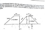
Transcribed Image Text:Two embankments loads on silty clay soils layers as shown below. Unit weights of the left
right embankments are 11 and 13 kN/m², respectively. Determine the stress increase
he embankments at point A that are loaded at a depth of 4 m below the ground
urface.
-3m
!Center line
1V:1H
Y= 11 kN/m
5m
y= 13 N/m
1V:1H
1V:1H

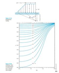
Transcribed Image Text:4.= yH
Figure 10.19
Embankment
loading
0.50
3.0
2.0
1.6
0.45
1.4
1.2
10
0.40
0.9
0.8
0.7
0.35
0.6
0.30
0.5
0.4
* 0.25
0.3
0.20
0.2
0.15
0.10
0.1
0.05
Figure 10.20
Osterberg's chart
for determination
of vertical stress
0.00
due to embank-
0.01
0.1
10
10.0
ment loading
Blz
327
DCegage Leaming 2014
Expert Solution
This question has been solved!
Explore an expertly crafted, step-by-step solution for a thorough understanding of key concepts.
Step by stepSolved in 4 steps with 1 images

Knowledge Booster
Learn more about
Need a deep-dive on the concept behind this application? Look no further. Learn more about this topic, civil-engineering and related others by exploring similar questions and additional content below.Similar questions
- *An embankment is proposed to construct on 10m thick clay deposit having the coefficient of volume compressibility as 2.7 x 10^-4 m?/kN. Determine the settlement of clay by the increase in vertical stress of 60 kN/m? due to the construction of embankment.arrow_forwardAn embankment consists of clay fill for which c′ = 25 kN/m2 and φ = 27° (from consolidated undrained tests with pore-pressure measurement). The average bulk unit-weight of the fill is 2 Mg/m3. Estimate the shear-strength in kPa of the material on a horizontal plane at a point 20 m below the surface of the embankment, if the pore pressure at this point is 180 kN/m2 as shown by a piezometer.arrow_forwardPatm = 10^5, P(water) = 1000 kg/m^3 ; Pair = 1.2 kg/m^3 ; g = 9.8m/s^2gage pressure Pg = P - Patmarrow_forward
- The figure shows a weir, the base of which is 6m below the ground. The necessary flow net has also been drawn assuming Kx = Kv = K. K = 0.005 m⁄sec. Compute the following: rate of seepage through the foundation in liters/sec. uplift pressure at“f”. uplift force per unit length measured along the axis of thearrow_forward(Use The Figure (10.20) to find the solution of this question) Two embankments loads on silty clay soils layers as shown below. Unit weights of the left and right embankments are 11 and 13 kN/m², respectively. Determine the stress increase under the embankments at point A that are loaded at a depth of 4 m below the ground surface. Center ine 1V:1H y= 11 kN/m 5m 13 N/m Figure 10.19 Embankment loading 050 3.0 20 045 14 12 LO 0.40 09 07 0.35 06 0.30 04 025 020 02 a10 Figure 10.20 Osterberg's chart for determination of vertical stress 0.00 TT TT due to embank- 100 ment koading 327 HEAIarrow_forward2.3. For the circular footing shown in Figure (Q.43, estimate the immediate settlement at the center of footing [Hint: for round base convert to an equivalent square]arrow_forward
- Q2. Analyse the stability of concrete gravity dam shown in the figure for the usual and unusual loading combinations. +70m 90m 1V:1H +0.0m Given data: f = 0.85, ø = 0.60, 7, = 6000 kN / m, o = 30000 kN / m² , of = 4000KN/m², Y con = 24 kN / m² , Yw= 10KN/ m , normal operating level is 70m, ice load is 60kN/m, silt height hs=5m., Y,=11kN/m, 0=32°.arrow_forwardIf in Figure 8.19 B₁ = 5.0 m, B₂=3.0 m, H = 4 m, z = 3 m, and the embankment applies a force of 137 kN/m2, the stress increase experienced 3 m (z = 3 m) below the bottom right corner point of the figure is, B₂- ** FIGURE 8.19 Embankment loading 105.58 kN/m² 62.34 kN/m² Ⓒ 150.78 kN/m² Ⓒ224.88 kN/m² -9-ylarrow_forward(Use The Figure (10.20) to find the solution of this question) An embankment load on a silty clay soil layer as shown below. Determine the stress increase under the embankment at points A and B that are loaded at a depth of 6 m below the ground surface. 5m 1H:2V 1H:2V 1H:1V 8 m y-18 kN/m y-18 kN/m 6 m 4. y Figure 10.19 Embankment loading 050 TTTT 3.0 20 16 045 14 12 LO 040 09 07 035 06 030 05 04 - 025 03 020 02 015 a.10 Figure 10.20 Osterberg's chart for determination of vertical stress 0.00 due to embank- 0.01 0.1 10 100 ment loading 327arrow_forward
- A trapezoidal channel with bottom width 3.5 m and side slopes 1H:1V on the left and 1.5H:1V on the right, with n = 0.016, and a bed slope of 2.6 in 10000 carries a discharge of 8 m³/s. Determine the normal depth and the average shear stress on the channel bed.arrow_forwardFor a linear stress variation over the base of the dam and neglecting hydrostatic uplift. 20 m 120- 1 som 6. Locate where the resultant crosses the base a. 5.59 m b. 6.28 m c. 8.42 m d. 10.51 m 7. Compute the maximum compressive stress at the base a. 1390 kPa b. 1186 kPa c. 463 kPa d. 508 kPaarrow_forwardQuestion 11 A rectangular channel with width = 10 meters and depth = 3 meters has a flow slope of 0.001 and roughness n = 0.025. The flow rate is 80 m/s. Determine the shear stress on the channel in Pascalsarrow_forward
arrow_back_ios
SEE MORE QUESTIONS
arrow_forward_ios
Recommended textbooks for you

 Structural Analysis (10th Edition)Civil EngineeringISBN:9780134610672Author:Russell C. HibbelerPublisher:PEARSON
 Principles of Foundation Engineering (MindTap Cou...Civil EngineeringISBN:9781337705028Author:Braja M. Das, Nagaratnam SivakuganPublisher:Cengage Learning
 Fundamentals of Structural AnalysisCivil EngineeringISBN:9780073398006Author:Kenneth M. Leet Emeritus, Chia-Ming Uang, Joel LanningPublisher:McGraw-Hill Education
 Traffic and Highway EngineeringCivil EngineeringISBN:9781305156241Author:Garber, Nicholas J.Publisher:Cengage Learning


Structural Analysis (10th Edition)
Civil Engineering
ISBN:9780134610672
Author:Russell C. Hibbeler
Publisher:PEARSON

Principles of Foundation Engineering (MindTap Cou...
Civil Engineering
ISBN:9781337705028
Author:Braja M. Das, Nagaratnam Sivakugan
Publisher:Cengage Learning

Fundamentals of Structural Analysis
Civil Engineering
ISBN:9780073398006
Author:Kenneth M. Leet Emeritus, Chia-Ming Uang, Joel Lanning
Publisher:McGraw-Hill Education


Traffic and Highway Engineering
Civil Engineering
ISBN:9781305156241
Author:Garber, Nicholas J.
Publisher:Cengage Learning