Structural Analysis
6th Edition
ISBN: 9781337630931
Author: KASSIMALI, Aslam.
Publisher: Cengage,
expand_more
expand_more
format_list_bulleted
Concept explainers
Question
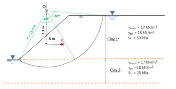
A level site underlain by fully saturated clays is cut over a few days as shown in the figure below. The water table is located at the ground surface across the site. Determine the resisting moment in kN.m for the circular slip surface depicted in the Figure below shortly after excavation.
Consider the soil wedge above the circular slip surface as a single free body, whose plane area is equal to 100 m2 and the centre of gravity of the soil wedge is given at Point C.

Transcribed Image Text:THE
R = 13.0 m
O
60⁰
7.3 m
40⁰
5m
Clay 1:
Clay 2:
Ymoist = 17 kN/m³
Ysat = 18 kN/m³
Su = 50 kPa
Ymoist = 17 kN/m³
Ysat = 18 kN/m³
Su = 25 kPa
Expert Solution
This question has been solved!
Explore an expertly crafted, step-by-step solution for a thorough understanding of key concepts.
Step by stepSolved in 5 steps with 2 images

Knowledge Booster
Learn more about
Need a deep-dive on the concept behind this application? Look no further. Learn more about this topic, civil-engineering and related others by exploring similar questions and additional content below.Similar questions
- A sample of soil (0.1 m X 0.1 m) is subjected to the forces shown in Figure below. Determine (a) σ1, σ3, and α;(b) the maximum shear stress; and (c) the stresses on a plane oriented at 30° counterclockwise from the major principal stress plane.arrow_forwardAn embankment load on a silty clay soil layer as shown below. Determine the stress increase under the embankment at points A and B that are loaded at a depth of 6 m below the ground surface, please use figure (10.20). 5 m 1Н:2V, 1H:2V 1H:1V 8 m y=18 kN/m y=18 kN/m" 6 m : B Figure 10.19 Embankment loading 0.50- 3.0 20 16 0.45- 14 1.2 LO 0.40 - 0.9 0.8 0.7 0.35 - 0.6 030- 05 04 * 025 - 03 0.20 - 0.2 0.15 - 0.10 - 0.1 0.05- Figure 10.20 Osterberg's chart for determination of vertical stress 0.00 TI TT - due to embank- 01 0.1 10 ment loading 100 327arrow_forward6 decimal places for the solutionarrow_forward
- 5-4 For the given soil profile and the piezometric surfaces measured at the top of the two sand and gravel layers, determine the pore pressure and effective stress at points A, B, C, D, and E. Piezometers 2 m Ground surface 2 m Sand y = 18 kN/m3 Water table y_ 11m Y = 20 kN/m3 A 4 m Clay Y = 18 kN/m3 加。B 1Im 5 m Sand and gravel y = 22 kN/m3 2 m •D 5 m Clay Y = 19 kN/m3 Sand and gravel y = 23 kN/m3 %3D Cpyright byarrow_forwardProb. 3 The plan of a flexible rectangular loaded area is shown in Figure below. The uniformly distributed load on the flexible area, q, is 100 kN/m². Determine the increase in the vertical stress, Aoz, at a depth of z = 2 m below a. Point A b. Point B c. Point C 4 m 1.6 m 2 m 0.8 m q = 100 kN/m² A 1.2 m-arrow_forward
arrow_back_ios
arrow_forward_ios
Recommended textbooks for you

 Structural Analysis (10th Edition)Civil EngineeringISBN:9780134610672Author:Russell C. HibbelerPublisher:PEARSON
 Principles of Foundation Engineering (MindTap Cou...Civil EngineeringISBN:9781337705028Author:Braja M. Das, Nagaratnam SivakuganPublisher:Cengage Learning
 Fundamentals of Structural AnalysisCivil EngineeringISBN:9780073398006Author:Kenneth M. Leet Emeritus, Chia-Ming Uang, Joel LanningPublisher:McGraw-Hill Education
 Traffic and Highway EngineeringCivil EngineeringISBN:9781305156241Author:Garber, Nicholas J.Publisher:Cengage Learning


Structural Analysis (10th Edition)
Civil Engineering
ISBN:9780134610672
Author:Russell C. Hibbeler
Publisher:PEARSON

Principles of Foundation Engineering (MindTap Cou...
Civil Engineering
ISBN:9781337705028
Author:Braja M. Das, Nagaratnam Sivakugan
Publisher:Cengage Learning

Fundamentals of Structural Analysis
Civil Engineering
ISBN:9780073398006
Author:Kenneth M. Leet Emeritus, Chia-Ming Uang, Joel Lanning
Publisher:McGraw-Hill Education


Traffic and Highway Engineering
Civil Engineering
ISBN:9781305156241
Author:Garber, Nicholas J.
Publisher:Cengage Learning