
Power System Analysis and Design (MindTap Course List)
6th Edition
ISBN: 9781305632134
Author: J. Duncan Glover, Thomas Overbye, Mulukutla S. Sarma
Publisher: Cengage Learning
expand_more
expand_more
format_list_bulleted
Related questions
Question
VLL=240 IL=0.1 P1=19W P2=19W PINPUT=38W Please solve question 3 in report section

Transcribed Image Text:Theory:
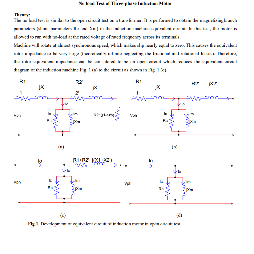
No load Test of Three-phase Induction Motor
The no load test is similar to the open circuit test on a transformer. It is performed to obtain the magnetizingbranch
parameters (shunt parameters Rc and Xm) in the induction machine equivalent circuit. In this test, the motor is
allowed to run with no-load at the rated voltage of rated frequency across its terminals.
Machine will rotate at almost synchronous speed, which makes slip nearly equal to zero. This causes the equivalent
rotor impedance to be very large (theoretically infinite neglecting the frictional and rotational losses). Therefore,
the rotor equivalent impedance can be considered to be an open circuit which reduces the equivalent circuit
diagram of the induction machine Fig. 1 (a) to the circuit as shown in Fig. 1 (d).
Vph
R1
jX
lo
>
Ic
Rc
Ic
Vph
Rc
ник
чик
lo
R2'
jx
2'
Im
R2" ((1-s)/s).
jXm
(a)
lo
R1+R2' j(X1+X2')
www.
Vph
R1
R2' jX2'
jX
1
lo
ပ
Ic
Rc
www
(b)
/lo
Im
jXm
lo
Im
Ic
Vph
jXm
Rc
www
Im
E
jXm
(c)
(d)
Fig.1. Development of equivalent circuit of induction motor in open circuit test

Transcribed Image Text:1. Connect the circuit as shown in the connection diagram in Figure 2.
127v
U
11
U
A
IM
127v
>
VLL1
V
V
No-
Shaft
127v
VLL2
W
12
W
A
Fig. 2. Induction motor open circuit test
2. Start the motor by ensuring the shaft is at no load condition.
3. For starting, increase the voltage to reach rated voltage.
4. Note the readings of voltmeter, ammeter and wattmeter by carefully and fill them in table 1
5. Reduce the voltage to zero and turn the main switch off.
Table 1: The measured parameters during open circuit test of the induction motor
Parameter
Measurement
Value
VLL
240
IL
P1
P2
Pinput
Report
1. Draw the circuit diagram of open circuit test. Give some explanations
2. Calculate the machine parameters that is can be obtained from No-Load test (Rc and Xm).
3. What is the power factor of the machine? Comment on its value.
4. Comment on the slip of the machine in this case.
5. What are the different losses that are present in an induction machine in this case?
Expert Solution
This question has been solved!
Explore an expertly crafted, step-by-step solution for a thorough understanding of key concepts.

Step by stepSolved in 2 steps with 1 images

Knowledge Booster

Similar questions
- Why is it necessary to conduct polarity tests on transformers?arrow_forwardThe shunt field winding of a shunt generator has a resistance of 80 ohms at 20⁰C. After several hours of continuous operation, the winding temperature rises to 50⁰C. How much is the winding resistance under this condition, Assume the resistance temperature coefficient of copper to be 0.004 ohm per degree at 0⁰C.arrow_forwardFor 4 pole d.c machine armature winding with a double layer progressive simplex wave winding with 23 number of slots answer the following: a How many coils are present? b What is the coil span in terms of number of slots? c What is commutator pitch in terms of commutator segments? d How many coils are there between two consecutive commutator segments? e How many parallel paths are present?arrow_forward
- Any chooses is correct?arrow_forward(Q1f, Draw and compare the per-phase electrical equivalent circuits of a transformer and of an induction motor. Using simple magnetic circuits, explain how the values of the magnetising (shunt) impedances compare in the two devices and what is the cause of the difference between the two? Figure 2. A transformer and an induction motor. Among other differences, one is typically rectangular, and the other one is round :Darrow_forwardFull solutions for the question with explanationarrow_forward
- Draw the per-phase equivalent circuit of a three-phase squirrel-cage induction machine. List all of the elements in the equivalent circuit and briefly state their functionarrow_forward9. How does the concept of magnetic saturation impact the performance of transformers and inductors?arrow_forwardDesign a winding diagram given the following specifications. • Simplex Wave Progressive Winding • No. of Poles = 4 • Turn/coil = 1 • Conductor/Slot = 2 • No. of Commutator Segments = 27 • No. of Slots = 27 %3Darrow_forward
- A 10-kVA, 1-phase transformer has a turn ratio of 300/23. The primary is connected to a 1500-V, 60 Hz supply. Find the secondary volts on open-circuit and the approximate values of the currents in the two windings on full-load. Find also the maximum value of the flux.arrow_forwardA 6 pole wave wound d.c. shunt generator has 500 conductors. A generator delivers 50 kW of power at 250 voltage at full load. The resistance of the field circuit is 125 2. Actual brush shift is 10°. Then find the demagnetizing and cross magnetizing ampere turns per pole and how many additional turns must be wound on each pole to eliminate the demagnetizing effect.arrow_forwardWhat conclusions we come up with after doing open circuit test on single phase transformer.arrow_forward
arrow_back_ios
SEE MORE QUESTIONS
arrow_forward_ios
Recommended textbooks for you
- Power System Analysis and Design (MindTap Course ...Electrical EngineeringISBN:9781305632134Author:J. Duncan Glover, Thomas Overbye, Mulukutla S. SarmaPublisher:Cengage Learning
Power System Analysis and Design (MindTap Course ...
Electrical Engineering
ISBN:9781305632134
Author:J. Duncan Glover, Thomas Overbye, Mulukutla S. Sarma
Publisher:Cengage Learning