Steel Design (Activate Learning with these NEW titles from Engineering!)
6th Edition
ISBN: 9781337094740
Author: Segui, William T.
Publisher: Cengage Learning
expand_more
expand_more
format_list_bulleted
Question
Read image pls

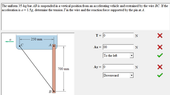
Transcribed Image Text:The uniform 35-kg bar AB is suspended in a vertical position from an accelerating vehicle and restrained by the wire BC. If the
acceleration is a = 1.5g, determine the tension T in the wire and the reaction force supported by the pin at A.
이
C
250 mm
T= |0
N
A
Ax = 00
B
To the left
N
700 mm
Ay = 0
N
Downward
X X X X >
Expert Solution
This question has been solved!
Explore an expertly crafted, step-by-step solution for a thorough understanding of key concepts.
Step by stepSolved in 2 steps with 1 images

Knowledge Booster
Similar questions
- A beam is part of the framing system for the floor of an office building. The floor is subjected to both dead loads and live loads. The maximum moment caused by the service dead load is 45 ft-kips, and the maximum moment for the service live load is 63 ft-kips (these moments occur at the same location on the beam and can therefore be combined). a. If load and resistance factor design is used, determine the maximum factored bending moment (required moment strength). What is the controlling AISC load combination? b. What is the required nominal moment strength for a resistance factor of 0.90? c. If allowable strength design is used, determine the required moment strength. What is the controlling AISC lead combination? d. What is the required nominal moment strength for a safety factor of 1.67?arrow_forwardusing Figure 5-27, what is the advantage of the suspended type magnet over the other two types of magnets?arrow_forwardVerify the value of Zx for a W1850 that is tabulated in the dimensions and properties tables in Part 1 of the Manual.arrow_forward
- Compute the nominal shear strength of an M107.5 of A572 Grad 65 steel.arrow_forwardFor the beam shown: (a) determine the distance a for which the maximum positive and negative bending moments in the beam are equal; and (b) draw the corresponding shear and bending moment diagrams for the beam.arrow_forwardThe data in Table 1.5.3 were obtained from a tensile test of a metal specimen with a rectangular cross section of 0.2011in.2 in area and a gage length (the length over which the elongation is measured) of 2.000 inches. The specimen was not loaded to failure. a. Generate a table of stress and strain values. b. Plot these values and draw a best-fit line to obtain a stress-strain curve. c. Determine the modulus of elasticity from the slope of the linear portion of the curve. d. Estimate the value of the proportional limit. e. Use the 0.2 offset method to determine the yield stress.arrow_forward
- A tensile test was performed on a metal specimen with a diameter of 1 2 inch and a gage length (the length over which the elongation is measured) of 4 inches. The dam were plotted on a load-displacement graph. P vs. L. A best-fit line was drawn through the points, and the slope of the straight-line portion was calculated to be P/L =1392 kips/in. What is the modulus of elasticity?arrow_forwardA column in a building is subjected to the following load effects: 9 kips compression from dead load 5 kips compression from roof live load 6 kips compression from snow 7 kips compression from 3 inches of rain accumulated on the roof 8 kips compression from wind a. If lead and resistance factor design is used, determine the factored load (required strength) to be used in the design of the column. Which AISC load combination controls? b. What is the required design strength of the Column? c. What is the required nominal strength of the column for a resistance factor of 0.90? d. If allowable strength design is used, determine the required load capacity (required strength) to be used in the design of the column. Which AISC load combination controls? e. What is the required nominal strength of the column for a safety factor of 1.67?arrow_forwardA tensile test was performed on a metal specimen having a circular cross section with a diameter 0. 510 inch. For each increment of load applied, the strain was directly determined by means of a strain gage attached to the specimen. The results are, shown in Table: 1.5.1. a. Prepare a table of stress and strain. b. Plot these data to obtain a stress-strain curve. Do not connect the data points; draw a best-fit straight line through them. c. Determine the modulus of elasticity as the slope of the best-fit line.arrow_forward
arrow_back_ios
arrow_forward_ios
Recommended textbooks for you
 Steel Design (Activate Learning with these NEW ti...Civil EngineeringISBN:9781337094740Author:Segui, William T.Publisher:Cengage Learning
 Materials Science And Engineering PropertiesCivil EngineeringISBN:9781111988609Author:Charles GilmorePublisher:Cengage Learning
 Residential Construction Academy: House Wiring (M...Civil EngineeringISBN:9781285852225Author:Gregory W FletcherPublisher:Cengage Learning
 Engineering Fundamentals: An Introduction to Engi...Civil EngineeringISBN:9781305084766Author:Saeed MoaveniPublisher:Cengage Learning
 Residential Construction Academy: House Wiring (M...Civil EngineeringISBN:9781337402415Author:Gregory W FletcherPublisher:Cengage Learning

Steel Design (Activate Learning with these NEW ti...
Civil Engineering
ISBN:9781337094740
Author:Segui, William T.
Publisher:Cengage Learning

Materials Science And Engineering Properties
Civil Engineering
ISBN:9781111988609
Author:Charles Gilmore
Publisher:Cengage Learning

Residential Construction Academy: House Wiring (M...
Civil Engineering
ISBN:9781285852225
Author:Gregory W Fletcher
Publisher:Cengage Learning

Engineering Fundamentals: An Introduction to Engi...
Civil Engineering
ISBN:9781305084766
Author:Saeed Moaveni
Publisher:Cengage Learning

Residential Construction Academy: House Wiring (M...
Civil Engineering
ISBN:9781337402415
Author:Gregory W Fletcher
Publisher:Cengage Learning
