
Elements Of Electromagnetics
7th Edition
ISBN: 9780190698614
Author: Sadiku, Matthew N. O.
Publisher: Oxford University Press
expand_more
expand_more
format_list_bulleted
Related questions
Question
Please solve for all and include all steps. Thx
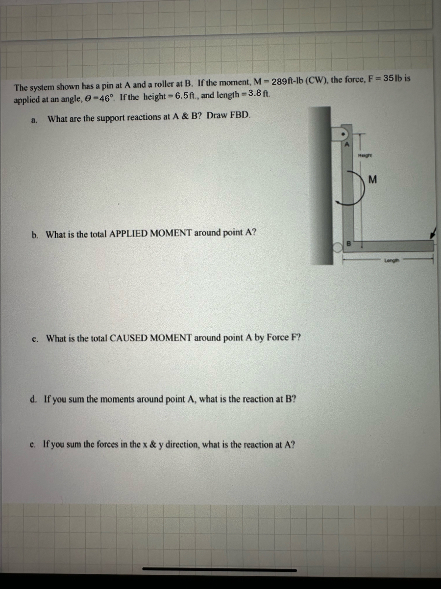

Transcribed Image Text:The system shown has a pin at A and a roller at B. If the moment, M = 289 ft-lb (CW), the force, F = 35 lb is
applied at an angle, 0=46°. If the height = 6.5 ft., and length = 3.8 ft.
a.
What are the support reactions at A & B? Draw FBD.
b. What is the total APPLIED MOMENT around point A?
c. What is the total CAUSED MOMENT around point A by Force F?
d. If you sum the moments around point A, what is the reaction at B?
c. If you sum the forces in the x & y direction, what is the reaction at A?
Height
M
Length
Expert Solution
This question has been solved!
Explore an expertly crafted, step-by-step solution for a thorough understanding of key concepts.

Step by stepSolved in 2 steps

Knowledge Booster

Similar questions
- I need handwritten only and lls correct if nott handwritten I'll dislikearrow_forwardProblem 3: Inputs: a = 12 in b = 12.75 in Use the scalar approach (not the cross product). The moment exerted by the weight about point E is 244 lb-in. Table not required, but feel free to use it if you like (a) What is the magnitude of the weight? (round this answer to the nearest whole number) (b) What is the moment exerted by the weight about point S? Problem 4: Inputs: a = 1.2 m b = 0.5 m P = 50 N We are going to put this system in equilibrium. We haven't talked much about equilibrium yet, but that's okay. In order for a body to be in equilibrium, we need the sum of the forces to equal zero, and the sum of the moments about any point to equal zero. S A Table not required, but feel free to use it if you like a FA 30° a E b 40° P b (a) Let's start by summing moments about point A. Determine the magnitude of FB such that EMA = 0. In other words, compute FB such that the net moment about point A is zero. (b) Now let's repeat the process at B. Sum moments about point B and compute the…arrow_forwarde. What is the moment caused by the force, F, -9641bf, on around POINT A on the block if 0 = 42°, a 4.6 ft., and b = 8.1ft.? F 0 b A f. What is the moment caused by the weight of the block, W=6731bf, (applied at the center of mass, which is in the middle of the block) around point A? g. What is the magnitude of the force, F2, necessary to create a resultant moment of zero from all forces on the block around A. h. Is the block in equilibrium (consider forces and moments)?arrow_forward
- Answer should be : Mo : 189.3 lb ft, O = 18.5 lb at 248 from positive axesarrow_forwardCompute the magnitude of the moment Mo of the 375-lb force about the axis 0-0. Assume F = 375 lb, d = 14 in., H = 10.6 in., h = 5.6 in., 0 = 32°, and = 69°. F d H Answer: Mo i Ib-in.arrow_forward6. use correct sig figarrow_forward
- Three forces F1, F2, and F3 are applied to a beam as shown in the figure. Determine the moments MA1, MA2, and MA3 about point A produced by each of the forces.arrow_forwardThe compound beam is supported by a rocker at B and is fixed to the wall at A. Part A: If it is hinged (pinned) together at C, determine the horizontal component of reaction at the support A. Neglect the thickness of the beam. Part B: Determine the vertical component of reaction at the support A. Part C: Determine the vertical component of reaction at the support B. Part D: Determine the direction of the moment at the support A. Part E: Determine the magnitude of the moment at the support A.arrow_forwardP{lease don't provide handwritten solution ..arrow_forward
- Q3/ Calculate the moment of the 90- N force about point O for the condition 0=15. Also, determine the value of e for which the moment about O is (b) zero and (c) a .maximum F = 90 N 800 mm O A 500 mmarrow_forward2a. If the load intensities w1=82 N/m, w2=176 N/m, and w3=102 N/m, determine the total moment (in N*m) caused by all these applied distributed forces about point A. Take counterclockwise as positive. Answer must include 1 place after the decimal point. 2c. Find out all of the support reactions components if applicable.arrow_forwardTwo forces L (parallel to the y-axis) and A (parallel to the z-axis) are applied at point Q on the assembly shown. The assembly is supported by a bearing at D. Answer the following questions: 1. What are the reactions at the support at D? R are force reactions and M are moment reactions. 2. Find the moment of force L about the x-axis.arrow_forward
arrow_back_ios
SEE MORE QUESTIONS
arrow_forward_ios
Recommended textbooks for you
- Elements Of ElectromagneticsMechanical EngineeringISBN:9780190698614Author:Sadiku, Matthew N. O.Publisher:Oxford University Press
 Mechanics of Materials (10th Edition)Mechanical EngineeringISBN:9780134319650Author:Russell C. HibbelerPublisher:PEARSON
 Thermodynamics: An Engineering ApproachMechanical EngineeringISBN:9781259822674Author:Yunus A. Cengel Dr., Michael A. BolesPublisher:McGraw-Hill Education
  Control Systems EngineeringMechanical EngineeringISBN:9781118170519Author:Norman S. NisePublisher:WILEY
 Mechanics of Materials (MindTap Course List)Mechanical EngineeringISBN:9781337093347Author:Barry J. Goodno, James M. GerePublisher:Cengage Learning
 Engineering Mechanics: StaticsMechanical EngineeringISBN:9781118807330Author:James L. Meriam, L. G. Kraige, J. N. BoltonPublisher:WILEY
Elements Of Electromagnetics
Mechanical Engineering
ISBN:9780190698614
Author:Sadiku, Matthew N. O.
Publisher:Oxford University Press
Mechanics of Materials (10th Edition)
Mechanical Engineering
ISBN:9780134319650
Author:Russell C. Hibbeler
Publisher:PEARSON
Thermodynamics: An Engineering Approach
Mechanical Engineering
ISBN:9781259822674
Author:Yunus A. Cengel Dr., Michael A. Boles
Publisher:McGraw-Hill Education
Control Systems Engineering
Mechanical Engineering
ISBN:9781118170519
Author:Norman S. Nise
Publisher:WILEY
Mechanics of Materials (MindTap Course List)
Mechanical Engineering
ISBN:9781337093347
Author:Barry J. Goodno, James M. Gere
Publisher:Cengage Learning
Engineering Mechanics: Statics
Mechanical Engineering
ISBN:9781118807330
Author:James L. Meriam, L. G. Kraige, J. N. Bolton
Publisher:WILEY