
Materials Science And Engineering Properties
1st Edition
ISBN: 9781111988609
Author: Charles Gilmore
Publisher: Cengage Learning
expand_more
expand_more
format_list_bulleted
Related questions
Concept explainers
Question
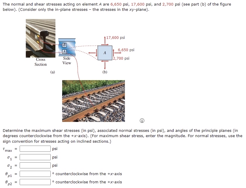

Transcribed Image Text:The normal and shear stresses acting on element A are 6,650 psi, 17,600 psi, and 2,700 psi (see part (b) of the figure
below). (Consider only the in-plane stresses - the stresses in the xy-plane).
117,600 psi
B
A
6,650 psi
A
Cross
Side
|2,700 psi
Section
View
(a)
(b)
Determine the maximum shear stresses (in psi), associated normal stresses (in psi), and angles of the principle planes (in
degrees counterclockwise from the +x-axis). (For maximum shear stress, enter the magnitude. For normal stresses, use the
sign convention for stresses acting on inclined sections.)
max =
psi
psi
02
psi
%3D
° counterclockwise from the +x-axis
p1
p2
° counterclockwise from the +x-axis
Expert Solution
This question has been solved!
Explore an expertly crafted, step-by-step solution for a thorough understanding of key concepts.

Step by stepSolved in 2 steps with 3 images

Knowledge Booster


Learn more about
Need a deep-dive on the concept behind this application? Look no further. Learn more about this topic, civil-engineering and related others by exploring similar questions and additional content below.Similar questions
- EB and FG are two planes inside a soil element ABCD as shown in Figure 10.50. Stress conditions on the two planes are Plane EB: EB = 25 kN/m2; EB = +10 kN/m2 Plane FG: FG = 10 kN/m2; FG = 5 kN/m2 (Note: Mohrs circle sign conventions for stresses are used above) Given ; = 25, determine: a. The maximum and minimum principal stresses b. The angle between the planes EB and FG c. The external stresses on planes AB and BC that would cause the above internal stresses on planes EB and FGarrow_forwardTwo line loads q1 and q2 of infinite lengths are acting on top of an elastic medium, as shown in Figure P8.6. Find the vertical stress increase at A.arrow_forwardThe data in Table 1.5.3 were obtained from a tensile test of a metal specimen with a rectangular cross section of 0.2011in.2 in area and a gage length (the length over which the elongation is measured) of 2.000 inches. The specimen was not loaded to failure. a. Generate a table of stress and strain values. b. Plot these values and draw a best-fit line to obtain a stress-strain curve. c. Determine the modulus of elasticity from the slope of the linear portion of the curve. d. Estimate the value of the proportional limit. e. Use the 0.2 offset method to determine the yield stress.arrow_forward
- A tensile test was performed on a metal specimen having a circular cross section with a diameter 0. 510 inch. For each increment of load applied, the strain was directly determined by means of a strain gage attached to the specimen. The results are, shown in Table: 1.5.1. a. Prepare a table of stress and strain. b. Plot these data to obtain a stress-strain curve. Do not connect the data points; draw a best-fit straight line through them. c. Determine the modulus of elasticity as the slope of the best-fit line.arrow_forwardCompare the engineering and true secant elastic moduli for the natural rubber in Example Problem 6.2 at an engineering strain of 6.0. Assume that the deformation is all elastic.arrow_forwardThe results of a tensile test are shown in Table 1.5.2. The test was performed on a metal specimen with a circular cross section. The diameter was 3 8 inch and the gage length (The length over which the elongation is measured) was 2 inches. a. Use the data in Table 1.5.2 to produce a table of stress and strain values. b. Plot the stress-strain data and draw a best-fit curve. c. Compute the, modulus of elasticity from the initial slope of the curve. d. Estimate the yield stress.arrow_forward
- A 9 ft wide and infinitely long flexible strip load of 800 lb/ft2 is placed on an elastic medium as shown in Figure P8.7. Find the vertical stress increase at points A, B, and C located 3 ft below the surface.arrow_forwardEstimate the elastic and plastic strain at the ultimate tensile strength in the low-carbon steel specimen in Figure 6.16.arrow_forwardHow does a tensile stress differ from a compressive stress?arrow_forward
arrow_back_ios
arrow_forward_ios
Recommended textbooks for you
- Materials Science And Engineering PropertiesCivil EngineeringISBN:9781111988609Author:Charles GilmorePublisher:Cengage Learning
 Principles of Geotechnical Engineering (MindTap C...Civil EngineeringISBN:9781305970939Author:Braja M. Das, Khaled SobhanPublisher:Cengage Learning
 Principles of Foundation Engineering (MindTap Cou...Civil EngineeringISBN:9781337705028Author:Braja M. Das, Nagaratnam SivakuganPublisher:Cengage Learning
  Steel Design (Activate Learning with these NEW ti...Civil EngineeringISBN:9781337094740Author:Segui, William T.Publisher:Cengage Learning
 Engineering Fundamentals: An Introduction to Engi...Civil EngineeringISBN:9781305084766Author:Saeed MoaveniPublisher:Cengage Learning
 Principles of Foundation Engineering (MindTap Cou...Civil EngineeringISBN:9781305081550Author:Braja M. DasPublisher:Cengage Learning
Materials Science And Engineering Properties
Civil Engineering
ISBN:9781111988609
Author:Charles Gilmore
Publisher:Cengage Learning
Principles of Geotechnical Engineering (MindTap C...
Civil Engineering
ISBN:9781305970939
Author:Braja M. Das, Khaled Sobhan
Publisher:Cengage Learning
Principles of Foundation Engineering (MindTap Cou...
Civil Engineering
ISBN:9781337705028
Author:Braja M. Das, Nagaratnam Sivakugan
Publisher:Cengage Learning
Steel Design (Activate Learning with these NEW ti...
Civil Engineering
ISBN:9781337094740
Author:Segui, William T.
Publisher:Cengage Learning
Engineering Fundamentals: An Introduction to Engi...
Civil Engineering
ISBN:9781305084766
Author:Saeed Moaveni
Publisher:Cengage Learning
Principles of Foundation Engineering (MindTap Cou...
Civil Engineering
ISBN:9781305081550
Author:Braja M. Das
Publisher:Cengage Learning