Introductory Circuit Analysis (13th Edition)
13th Edition
ISBN: 9780133923605
Author: Robert L. Boylestad
Publisher: PEARSON
expand_more
expand_more
format_list_bulleted
Question
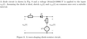
please draw a neat sketch of the graph and please show step by step working and explanations how you got the answer thank you

Transcribed Image Text:A diode circuit is shown in Fig. 8 and a voltage 10 sin(2π1000t) V is applied to the input
Vin(t). Assuming the diode is ideal, sketch vin(t) and vout (t) on common axes over a suitable
interval.
R
D
+
+
R
Vin(t)
Vout (t)
4V
+
Figure 8: A wave-shaping diode-resistor circuit.
Expert Solution
This question has been solved!
Explore an expertly crafted, step-by-step solution for a thorough understanding of key concepts.
Step by stepSolved in 2 steps with 3 images

Knowledge Booster
Similar questions
- Question 1: In the circuit shown below, the output (Vo = 10V Max.) Unipolar. The frequency of Primary is 60 Hz. The diodes are Silicon with VD = 0.7V. a. Sketch the output without a Capacitor. b. Determine Voc without a Capacitor. c. Sketch Vs (at the Secondary). d. Determine Voc with a Capacitor of 10 uF across RL. e. Determine the RMS Value of Vp (at the Primary). f. PIV (Peak Inverse Voltage). 10:1 Output C. 22 k1 All diodes are IN4001. | 00000arrow_forwardVi (t) = 10.sinwt Does not pass positive alternans when Volt input voltage is applied, only Design and explain two different circuits that pass negative alternans. Draw the input and output voltages. What are the types of these circuits? (Note: You can use the ideal diode approach)arrow_forwardmodels Diodes-Piece-wise Problem #1 In the circuit shown below, the voltage source Vin is given by the sketch. Assuming an ideal diode, sketch the waveform resulting at Vout. Use the axis at the bottom to help you sketch the voltage output. 10Ω Vin +7V -7V + Vin Vin AA 1 3 4 5 1 2 D 3 5 V 4 + Vout 5 6 ➡t (ms) +++t (ms) 6arrow_forward
- A clipper circuit based on diodes are simple way to modify waveform in mechatronics. Assume that the two diodes shown in the circuit below are ideal diodes. If the input voltage in the circuit is a 1 kHz sinusoid with peak amplitude of 8V, sketch the Va.. (t) 10 kO 8V 10 kO Vin Vin(t) D2 Vout(t) RL Ims D1 6V -8V 4V Page | 1arrow_forwardPlease answer in typing formatarrow_forwardA clipper circuit based on diodes are simple way to modify waveform in mechatronics. Assume that the two diodes shown in the circuit below are ideal diodes. If the input voltage in the circuit is a 1 kHz sinusoid with peak amplitude of 8V, sketch the Vaue (t). 10 k. 8V 10 kN. D2 RL Vourlt) Vin= Vin(t) Ims D1 6V -8V 4V Page | 1arrow_forward
- Vin = 10 mV Sin (wt) HH inf 1. For the Diode Circuits shown below, Vd-0.7v a. Draw the small signal eq. circuit find Vo (AC+DC) b. C. Sketch the output waveform Vo (AC+DC) V1 vin D Find the cascaded voltage gain Yout/Vin of the follo I'C 5 R2 25 11 1m D1 dio R1 300 Voarrow_forwardIn the circuit shown below. Let V-33 V and i,-28 mA and Voo -0.7 V: iD Vcos(at)V For t = 0s, the current in the diode equals: Ca. 0 mA Cb. 2 mA Cc. 4 mA Od. 2 mA Ift = T/4, then the current in the diode equals: Ca. 8.92 mA Ob. 5.71 mA Oc 7.14 mA Od. 4.57 ma Ift- T/2, then the current in the diode equals: Ca. 10.39 mA Cb. 16.39 mA Oc 14.39 mA Od. 12.39 mAarrow_forwardSuppose we have a 10-Hz sinusoidal voltage source, vin(t). Draw the diagram of a circuit that clamps the positive peaks to -4 V. The circuit should be composed of ideal diodes, dc voltage sources, and other components as needed. List any constraints that should be observed in selecting component values. Be sure to label the terminals across which the clamped output waveform vo(t) appears.arrow_forward
- The input voltage (vin) of the following circuit is a sinusoidal signal with an amplitude of 2Vrms,consider a silicon diode.graph the output voltage ?? and the current across the resistor.arrow_forwardPlease try to answer in typing format please ASAP for the like y Please I will like it please I thank you for your positive responsearrow_forwardDesign a circuit so that the steady-state output voltage is V. = 20 V (DC) for the input voltage of V, (t) = 10.sinwt (V) and explain how it satisfies this output. (You may use ideal diodes) Sketch the output voltage between 0-3T/2.arrow_forward
arrow_back_ios
SEE MORE QUESTIONS
arrow_forward_ios
Recommended textbooks for you
 Introductory Circuit Analysis (13th Edition)Electrical EngineeringISBN:9780133923605Author:Robert L. BoylestadPublisher:PEARSON
 Delmar's Standard Textbook Of ElectricityElectrical EngineeringISBN:9781337900348Author:Stephen L. HermanPublisher:Cengage Learning
 Programmable Logic ControllersElectrical EngineeringISBN:9780073373843Author:Frank D. PetruzellaPublisher:McGraw-Hill Education
 Fundamentals of Electric CircuitsElectrical EngineeringISBN:9780078028229Author:Charles K Alexander, Matthew SadikuPublisher:McGraw-Hill Education
 Electric Circuits. (11th Edition)Electrical EngineeringISBN:9780134746968Author:James W. Nilsson, Susan RiedelPublisher:PEARSON
 Engineering ElectromagneticsElectrical EngineeringISBN:9780078028151Author:Hayt, William H. (william Hart), Jr, BUCK, John A.Publisher:Mcgraw-hill Education,

Introductory Circuit Analysis (13th Edition)
Electrical Engineering
ISBN:9780133923605
Author:Robert L. Boylestad
Publisher:PEARSON

Delmar's Standard Textbook Of Electricity
Electrical Engineering
ISBN:9781337900348
Author:Stephen L. Herman
Publisher:Cengage Learning

Programmable Logic Controllers
Electrical Engineering
ISBN:9780073373843
Author:Frank D. Petruzella
Publisher:McGraw-Hill Education

Fundamentals of Electric Circuits
Electrical Engineering
ISBN:9780078028229
Author:Charles K Alexander, Matthew Sadiku
Publisher:McGraw-Hill Education

Electric Circuits. (11th Edition)
Electrical Engineering
ISBN:9780134746968
Author:James W. Nilsson, Susan Riedel
Publisher:PEARSON

Engineering Electromagnetics
Electrical Engineering
ISBN:9780078028151
Author:Hayt, William H. (william Hart), Jr, BUCK, John A.
Publisher:Mcgraw-hill Education,